Eng-Tips is the largest engineering community on the Internet

Intelligent Work Forums for Engineering Professionals

  • Congratulations waross on being selected by the Tek-Tips community for having the most helpful posts in the forums last week. Way to Go!

Good Day Group, I am having an 1

Status
Not open for further replies.

cliff turnell

Mechanical
May 7, 2019
22
0
0
US
Good Day Group,


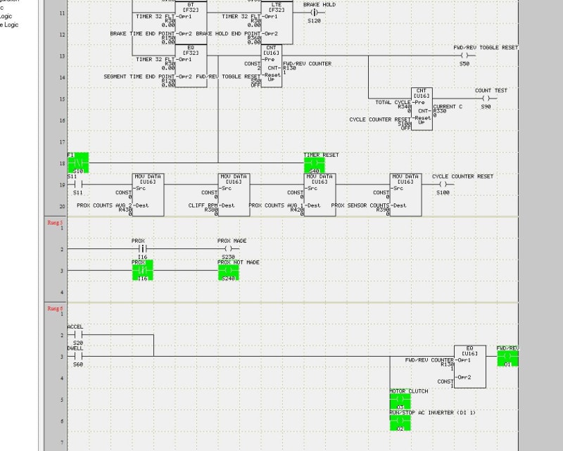
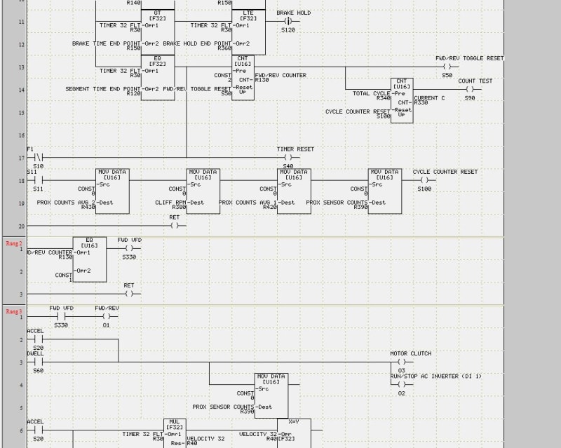
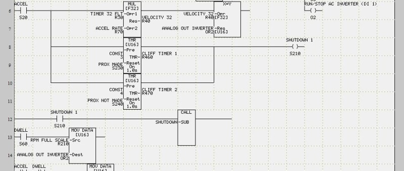
I am having an issue between my logic and the VFD that is controlling my motor. The VFD is an Automation Direct GS1. In my logic O2 is run/stop and O1 is direction (closed = CW and open = CCW, rung 6, line 3). What I am trying to accomplish is "if counter is equal to 1 then energize coil" (top rung line 15)and when the coil goes high the corresponding N.O. contact on rung 6, line 3 will close and energize coil O1 to change direction. For some reason I cannot get O1 to change states and am not sure if it might be my logic or an issue with the VFD. It seems pretty straight forward to me but obviously I am missing something and am hoping another set of eyes night be able to see something I am missing. For reference rung 4 (the top rung) is timing and rung 6 is motion. Thank you all in advance and have a great day!


Regards,
Cliff
 
 https://files.engineering.com/getfile.aspx?folder=c642f182-8adb-4684-a1de-bf3feeaefcbd&file=logic.JPG
Replies continue below

Recommended for you

What PLC is that, a TECO or LOGO!, or a Direct Logic maybe?

When monitoring does the rest of the rung go true but just O1 never goes active?
Or does O1 go active but you never see the drive respond to it?


Since that is only a code snippet I can't tell if you have any more O1's anywhere. Is that the single and only one in the program?

Keith Cress
kcress -
 
The PLC is an EZ420 made by EZ Automation, now obsolete but this is what I have to work with. Based on the indicator lights it looks like O1 is going high with every pass regardless of count state. This is the only O1 in the program. If you would like I have a PDF of the entire logic ( 6 rungs) that I could share. As a little backstory I am trying to resurrect an E-Stop test bench while teaching myself logic at the same time, a little cumbersome but getting there.
 
Apparently my eyes are not as good as I thought! Upon closer inspection the indicator light for O1 is NOT going high which explains why I am only going 1 direction so the issue must be with the logic...
 
Ah, an EZ420 made by EZ Automation..? I thought those were just user interfaces (HMIs).


So, do you have a "Monitor Mode" that shows the running state of the viewed page of code? This is NOT the LEDs on the device but usually is part of the development system that you're using to look at the code.

You can post the full code as a PDF and we/I may be able to spot the problem.

Keith Cress
kcress -
 
I do have a monitor mode which shows if registers are energized or not but only at start up, there is not a way to monitor the logic or individual registers in real time (at least according to tech support). Here is a little back story concerning this program, we have an E-Stop test bench that I have been tasked with resurrecting (it was mothballed for about 8 years and the original program was lost). I was given a snippet of code and have been working at turning it into a fully functional, fully programmable working piece. The test bench is a 3 phase motor/clutch combo that is driving a planetary gearhead and inertia wheel (inertia wheel has slots cut into it that are read by the prox sensor for RPM control via PID) with a EMP brake in between the clutch and gearhead. The motor is to ramp to X RPM, dwell, E-Stop, wait (to let EMP brake cool) and do it again in the other direction (CW and CCW = 1 cycle) until X cycles have been completed. The test is to see how many cycles of "reflected load from the inertia wheel" the pinion can handle. I have attached a couple of pics for reference and the complete (so far) logic and the rungs are situated as follows:

RUNG 1: MOVE PANEL BITS TO SYSTEM DISCRETE TO START PROGRAM WHEN F1 IS PUSHED
RUNG 2: STATIC CALCULATIONS, CONVERT TIMING INTEGERS TO FLOATING POINT (LINES 1 AND 2), SET UP TIME LINE FOR MOTOR RAMP, DWELL, STOP (LINES 5-8), SCALE ANALOG SIGNAL (LINES 9-13, NEEDS WORK) AND SCALE BRAKE SIGNAL (LINE 15)
RUNG 3: TIMERS TO CONTROL ACCEL, DWELL, BRAKE, BRAKE HOLD AND WAIT INTERVALS ( TIMES SET ON HMI)
RUNG 4: TIMING OF PROGRAM ITSELF (WHEN F1 IS PUSHED START OVERALL TIMER, CONVERT TO FLOATING POINT AND ACCEL, DWELL, BRAKE, BRAKE HOLD AND WAIT BASED ON TIMERS IN RUNG 3 (LINES 1-11). EACH TIME "SEGMENT TIME END POINT" IS REACHED IT EQUALS 1/2 CYCLE, LINE 19 IS A COUNTER/CYCLE RESET WHEN TEST IS FINISHED (F2 ON HMI)
RUNG 5: SETTING A BIT BASED ON IF THE PROX SENSOR IS HIGH OR LOW THAT IS TIED TO A TIMER ON TUNG 6 TO SHUT DOWN IF NO CHANGE IS SEEN DURING MOTION CYCLE
RUNG 6: THERE IF NEEDED FOR NOW
RUNG 7: MOTION: ENGAGING MOTOR/CLUTCH AND SETTING DIRECTION VIA VFD (LINES 2, 3) SETTING ACCELERATION AND VELOCITY (NEEDS WORK) AND TIMERS FOR SHUTDOWN, (LINE 6) AND MOVING SCALED VALUES TO VFD FOR DWELL (LINE 13) AND STOP (line 15)
RUNG 8: BRAKING: SEND SCALED VALUE TO BRAKE (LINE 1), CHECK # OF COUNTS AND OVERALL AVERAGE (LINE 4), SEND FULL SCALE VALUE TO BRAKE FOR HOLDING ( LINE 13) AND RELEASE (LINE 15)


Thank you in advance for your time and any insight in sincerely appreciated.
gearhead-brake-clutch_jbgkxm.jpg
motor-clutch-brake_w1b6cq.jpg


Cliff; Thanks for the details and pics.

I haven't figured it out yet but without a running monitor (I sure don't see how just being shown the initial state is worth diddly squat!) I'd be trying to get running info out to see it.

If you have any spare outputs (Ox) I'd use them all as probes. Assign one to ACCEL, one to DWELL, and one to VFD_FWD, to see which is the problem. If you only have one spare output work thru each one until you find the problem. That will guide you to where the problem code is.

You might also parallel O1 with a spare to prove it's not a hardware problem with O1. If you have no spares commandeer one. Pick the easiest one to steal,(maybe RUN_STOP), that the program can still operate around.

Keith Cress
kcress -


Thank you for the insight! Please forgive my ignorance in advance but when you say to use a spare output as a probe ( I do have 1 available) what are you referring to (and would this be to the NO contacts on rung 7)?
 
I also wanted to mention that yesterday I removed the counter and FWD VFD coil on rung 4, line 15 and the corresponding N.O. FWD VFD contact on rung 7, line 3 and did see a output signal according to the indicator lights so I am assuming my code is funky somewhere...
 
So this is the state of the logic before F1 is pressed. What I do not understand is the R130 on line 13 is already at 1 and this is before the program has even started. Based on that what it seems to me to be happening is the R130 is "registering" 1 twice so there is no differentiation to make O1 go high and low. What I was expecting was for R130 to be at 0 to start which would make O1 not go high on the first "1/2 cycle", then after the first 1/2 cycle would be 1 causing O1 to go high, then 2 causing a reset back to 0. I tried using a comparator for this test instead of the NO contact but it appears to be the same result. Any ideas on how to get around this and/or what might be causing it?

LOGIC_2_mc5dxj.jpg
 
Thank you for the insight! Please forgive my ignorance in advance but when you say to use a spare output as a probe ( I do have 1 available) what are you referring to (and would this be to the NO contacts on rung 7)?

Yes!

Those contacts are outputs elsewhere in your logic. They just happen to be internalized.

You immediately follow the rung under study with a single simple rung. You make rung 8:

First to confirm the hardware isn't screwed-up follow rung7 with:

Code:
...O1             O5
---||-------------()-

If that's not it follow with:

Code:
..ACCEL           O5
---||-------------()-

then

Code:
..DWELL           O5
---||-------------()-

then

Code:
.FWD VFD          O5
---||-------------()-


Or whatever the spare output is.

One of those is not doing what you expect. This should show which.

Keith Cress
kcress -
 
So it turns out that FWD-VFD was not doing what I wanted it to do. For some reason it did not like being in the "timing" rung so I put it into it's own rung and I am now sending the signal as intended (high on 1 half and low on the other) but for some reason the VFD is not responding as it should (still staying in reverse) but at least the logic is doing what is is supposed to so now on to the next question "why are you being like that VFD"? Will keep you posted on outcome...

BOTH_DIRECTIONS_WORKING_iigwqw.jpg
 
Good job!
Always remember the way a PLC executes.
Top to bottom it does all LOGIC first. Output states are kept in memory and not physically sent to the actual output hardware until all LOGIC is completed. Once all logic is completed the PLC mass transfers the resulting memory output states to the physical outputs.

What does this mean to you? It means the last state of an output is the winner that gets a physical representation. This can cause a lot of confusion as you may look at a rung that sets an output and everything is saying the output should be happening but something else farther down the code can be altering that result.

If you're looking at a rung that should've had an active output and yet it doesn't it often means you have something later in the code killing the output. This goes for internalized outputs that later become contacts in later rungs.

As for the VFD. Remember that most VFDs want you to feedback the control voltage that they source from their own control circuit. Usually one takes in that VFD supplied voltage at the PLC output group's voltage input. Then when an output goes active it sends that VFD supplied voltage back to the inputs of the VFD. If you're not doing this it may be the problem. There are caveats about this too. You can't generally use that weak VFD source to do anything else. On a basic PLC you might only have one single output power source group. Trying to run a brake unit or something non VFD will cause problems and possibly malfunctions. Sometimes you have to use external relays to provide a limit on what gets the VFD source voltage.

Use a piece of wire to check that the VFD can be controlled using the screw terminals the PLC is diddling. Check the VFD parameters are set to allow the external control. Reverse can be locked out. The external control screws can be selected and wrong for your wiring. If you command reverse while the VFD is in forward it will decelerate to stopped over the programmed decel time. Once stopped it will accelerate over the programmed acceleration time to the set speed.

Be careful as the VFD output is lethal and you don't want to come in contact with it or confuse the screw terminals.


Keith Cress
kcress -
 
So I was able to narrow down the cause of the "uni-directional VFD". I changed my "source of frequency command" from 0-10V input to the potentiometer on the VFD and it is now toggling forward and reverse as expected. That makes some sense because I do not have everything completely squared away as far as the scaling of the 0-10V input signal and the PID for the closed loop. It appears that the final piece of this little puzzle is to get the VFD analog input signal properly squared away which should lead to the VFD supplying the proper voltage as you mentioned above. Now for the part of the exercise I am slightly dreading, I will make sure to study and ask good questions (because I know I will have a few). Again, thanks for the assistance!
 
Making headway.

0-10V inputs usually take a remote source whereas the digital inputs may not.

0-10V is very common and should work. You don't need the V input to change signs to change the motor's direction as that is handled by that digital input.

With the PLC's analog out disconnected see what the PLC is putting out on the two leads.

Most VFDs have a switch you must set telling the VFD you're supplying a current (4-20mA) or a voltage (0-10V).

I cannot see how the PLC could be stopping the VFD from going one way via the analog voltage input unless the analog signal is going to 0V during the missing direction phase.

Keith Cress
kcress -
 
A little more background info: the VFD is an Automation Direct GS1. I have double checked the settings on the VFD to confirm the the switch is set to V, the analog gain is 200% (to account for the -100% analog input offset), negative input offset polarity and that FWD and REV motion are enabled. When you mention to disconnect the analog out and see what the PLC is putting on the 2 leads are you referring to the the output and common of the IO module? To start I think my first issue is that my "RPM MAX" (line 9 of control and pid pic) is not specified which in turn I think will screw up the math for the "RPM SCALE ANALOG" (line 9 of control and pid pic also) which will in turn not be able to send proper "RPM FULL SCALE" data to OR2 (line 13 of motion logic pic, OR2 is the motor run signal - RPM SCALE ANALOG and RPM FULL SCALE are converted on line 11 of control and pid pic). The original associated HMI program has "RPM MAX" set as a read only setting, my thought process is that to control the acceleration (VELOCITY 32 on line 6 of motion control pic) and dwell rpm I need to install a PID to scale my rpm (0-3000) to the analog module ( 16 bit, 0-4095). Does that thought process make sense and if so could we possibly discuss PID setup? I have been researching the topic but am not solid on the parameters. I would think that my control variable would be RPM FULL SCALE (data being moved to inverter for dwell cycle, the output rpm I am looking) for and my process variable would either be CURRENT RPM (line 13 of control and pid pic) or TARGET/DWELL RPM (line 9 of control and pid pic) but from there I am in the dark without a candle. I threw a shot of the PID parameters up for hopefully good measure. If a small novel would need to be written concerning these questions I can be reached at (775) 888-8257 (direct line) or 1-800-568-4327, EXT 257. Hopefully I am dialing in but as evidenced by this diatribe I have a ways to go.
MOTION_LOGIC_ltebua.jpg
CONTROL_AND_PID_gecige.jpg
.
 
When you mention to disconnect the analog out and see what the PLC is putting on the 2 leads are you referring to the the output and common of the IO module?
Yes. The analog signal being sent to the VFD.

I think you may be trying to run before you've crawled. You should have the whole thing running just fine with some rational fixed speed in both directions first. Like 300rpm. Then try higher ones as confidence builds. Once you have that you will then know you have full control of the motor as needed.

Then and only then you do you start messing with PIDs. You need speed feedback to use PID, don't recall seeing that.


Keith Cress
kcress -
 
Thank you! As I was writing that diatribe yesterday it felt like I may have been thrashing in the deep end of the pool (I don't know what I don't know, thank you for setting me straight) . I will check the analog output signal as you had recommended to start and see what I am getting for direction control signal and concentrate on controlling the dwell speed with the program before I start worrying about accel times and the like. The speed feedback that would be used for PID is a proximity sensor ( tag-prox, I16 on page 7 of program) that is keeping counts via slots cut in the inertia wheel which will also be a function of the gearhead ratio that is being tested but that is for another day (you may be able to see the slots in the attached pic).
inertia_wheel-brake_yuwdi6.jpg
. I will report on directional output analog signal and ultimate speed control findings ASAP.
 
directional output analog signal

While you can reverse the drive with analog on a GS1 you'd be insane to do it. Use the digital FWD/REV and AVOID using the analog for such foolishness. All you need is some tiny offset to cause crazy machine behavior.

Also, if you are considering feedback for PID and getting it from the inertial mass what happens when the coupling breaks? The inertial mass starts slowing down and the PID speeds up the motor spinning a broken coupling??!! You need something to detect a speed difference between the motor and the inertial mass.

I'm using a Productivity 2000 PLC and one of the (HSI) HighSpeedInput modules. They handle two high speed inputs. You'd assign one each to motor shaft and the inertial load. You'd know instantly when they weren't in sync. They also have specific GSx drive stuff in them and PIDs.

Keith Cress
kcress -
 
Status
Not open for further replies.
Back
Top