Eng-Tips is the largest engineering community on the Internet

Intelligent Work Forums for Engineering Professionals

  • Congratulations waross on being selected by the Eng-Tips community for having the most helpful posts in the forums last week. Way to Go!

Good Day Group, I am having an 1

Status
Not open for further replies.

cliff turnell

Mechanical
May 7, 2019
22
US
Good Day Group,


I am having an issue between my logic and the VFD that is controlling my motor. The VFD is an Automation Direct GS1. In my logic O2 is run/stop and O1 is direction (closed = CW and open = CCW, rung 6, line 3). What I am trying to accomplish is "if counter is equal to 1 then energize coil" (top rung line 15)and when the coil goes high the corresponding N.O. contact on rung 6, line 3 will close and energize coil O1 to change direction. For some reason I cannot get O1 to change states and am not sure if it might be my logic or an issue with the VFD. It seems pretty straight forward to me but obviously I am missing something and am hoping another set of eyes night be able to see something I am missing. For reference rung 4 (the top rung) is timing and rung 6 is motion. Thank you all in advance and have a great day!


Regards,
Cliff
 
 https://files.engineering.com/getfile.aspx?folder=c642f182-8adb-4684-a1de-bf3feeaefcbd&file=logic.JPG
Replies continue below

Recommended for you

I apologize for not being clear concerning how I am changing motor directions with the GS1 VFD. I am using setting 1 of parameter 3-01 which is DI1 = run/stop (O2 in my logic) and DI2 = FWD/REV (O1 in the logic), the IO module being used is a 4 analog in/4 out and one of the outputs is being used for the O1 open/close signal and the other for the O2 run/stop. The pinion gear of the gearhead is the weak link that will break under the E-Stop condition and is being ramped up to dwell rpm slowly and should not ( I won't say will not as anything is possible) break during running. I have a rung that sets a bit if the prox sensor is high or low during the "wait period" (after E-Stop to allow for brake cooling) and if during acceleration the prox sensor does not detect a change within the first 2 seconds the shutdown sequence initiates which has been tested and works as designed. I have been angling to get a different PLC that is newer with more functionality but we have 2 of these EZO models and that is what I have to work with.
 
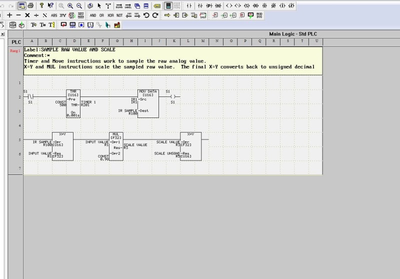
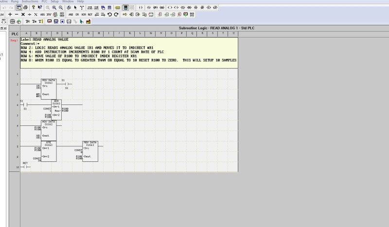
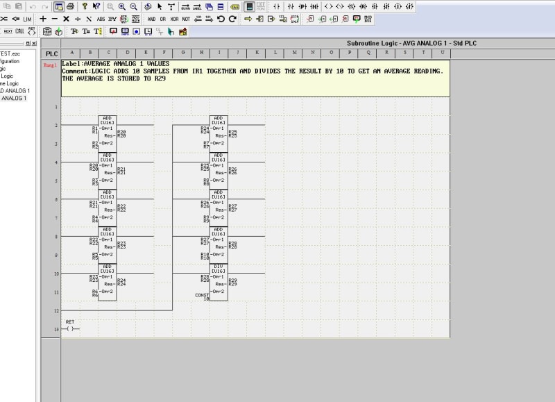
Over the weekend I did some more studying and it has dawned on me that I will need to create a new rung to be able to scale the output signal to the motor for total sped control. The line that I initially thought was for output scaling is actually for rate of velocity increase (line 9 of rung 2 of logic sent Aug 8th). The way that the EZ420 does scaling is a little different ( I have attached a screenshot of the example tech support sent to me). My question is "based on the logic that I attached on August 8th (power panel project) would you agree that I need to add a rung specifically to scale the analog output signal and if so would it be best to do it before or after my "motion" rung (rung 7). My thought process is to put the motor scaling signal rung right before motion rung (rung 7)so that during scanning the program the signal will be scaled as necessary prior to the motion rung (and subsequent outputs) being read and would also make sense based on the program "doing all logic prior to outputs". Currently the logic goes in these steps, calculations, timers, process timing, motion and braking. I have attached a pic of how the EZPLC does analog scaling, if I understand correctly the "IR1" source in the scaling example will be my "OR2" (analog out inverter), that "U16" value is converted to a floating point 32 bit value, that value is then multiplied by the "scale value" (I need 3000 RPM from a 16 bit module, my slope is 3000/4095 = .7326). I am not sure why the final "X=Y" conversion is needed to convert back to unsigned decimal. I have also attached a couple of pics concerning reading and averaging the analog signal, I am not sure if this logic somehow ties in or not but wanted to throw it up there in case it does. Any insight into this latest info is sincerely appreciated and if necessary I am willing to pay for some tutoring via a teamviewer session to get this project over the top.
scaling_for_output_ovfowt.jpg
read_analog_iix5h5.jpg
average_analog_c2shhm.jpg
. Again, thank you for your time and have a great day!
 
Status
Not open for further replies.

Part and Inventory Search

Sponsor

Back
Top