Eng-Tips is the largest engineering community on the Internet

Intelligent Work Forums for Engineering Professionals

  • Congratulations waross on being selected by the Tek-Tips community for having the most helpful posts in the forums last week. Way to Go!

Grundfos chiller loop pump with 30ft positive head sucking air. Is it the pump? 3

Status
Not open for further replies.

Hurtle

Industrial
May 5, 2020
3
0
0
TW
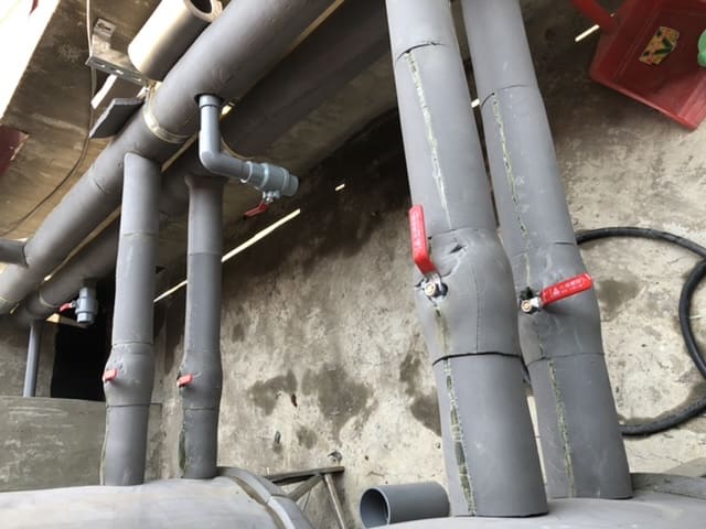
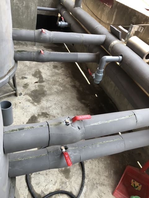
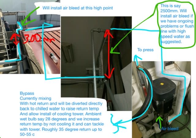
Hi, I’m in Taiwan and language problems limit the help I can get. We have a chiller pump line gravity fed from 4 floors above. Yesterday it stopped pumping and then started after air bleed 2 hours later. Chill water is 14 to degree Celsius.

I can’t see it is the PVC pipes my Taiwanese associate is blaming. Reason is I’d be hard pressed to design something that sends air 30ft down a 2” line to a pump.

Only other information I can add is it’s also returning 30ft back up to chiller tank of 3000 litres.

Pump grundfos CRI5-13A FJG A E HOOE 2 YEARS OLD USED 50 HOURS EACH WEEK
 
Replies continue below

Recommended for you

Gravity feed water systems can still develop air pockets that block the flow. The lines need to be continuously sloped down from the tank to the pump. Any local high point can trap air (or other gas) which restricts the flow and drop the NPSH available to the pump. Here is a link to a good article that describes the phenomenon.


Johnny Pellin
 
You need to look at the route of the pipes in section.

Where was this "air bleed"??

What do you mean by "blame the PVC pipes"?

You also need to look at velocity. If you can get to >1m/sec then you can normally sweep air bubbles out of pipe, even vertically down. Less than that and it could struggle to sweep air out.

Is this a closed system?

No real details here so very difficult to fault find from afar.

Remember - More details = better answers
Also: If you get a response it's polite to respond to it.
 
And look very carefully at the fittings nearest the pump. Even some very tiny leaks could be letting air get drawn in. These leaks could be so small that they wouldn't leak a noticeable amount of water.

= = = = = = = = = = = = = = = = = = = =
P.E. Metallurgy
 
Those are some great answers. Note we’ve not had a repeat yet. I’m concerned we will. It’s expensive to have the plant stopped.

1st response.... I’ve reviewed that 60 plus page article..thanks.

3rd response Fittings. Yes. I want the early start guy to check carefully around the pump before starting. Will do this tomorrow and Accept as you’ve indicated it could be such a small leak it won’t show/ it will suck air.

2nd response.....You need to look at the route of the pipes in section.

Where was this "air bleed"?? Good point... it’s the air bleed at the Grundfos pump itself. I was only getting the tiniest amount of air out then the pump would try to go again and build pressure before dropping again.

What do you mean by "blame the PVC pipes"? I’ll attempt to put an image up. The installer wants to change to steel. I can’t see this as the problem as indicated.

You also need to look at velocity. If you can get to >1m/sec then you can normally sweep air bubbles out of pipe, even vertically down. Less than that and it could struggle to sweep air out. We move 4000lph through a PVC pipe with an I.d. That looks to be about 50mm.

Is this a closed system? No, it’s an open tank system.

No real details here so very difficult to fault find from afar. I’m so aware of this and tried.... I see the holes in my report :) thanks all for responding.

Image... the upper run of pipe with open valve goes to chiller pump 30ft or so below. I cracked open that valve you see elbowed down for the hell of it wishing it was at the upper most spot in line. Will have a valve installed if we have a repeat. The lower run of pipe goes to a chiller and returns to the right tank to give us coolest water. There are 3 and the left one receives the warm return water.

We won’t go into why there are 3 tanks and all the connections. Let’s just say it’s an improvement on what was there before. The suspicion is we developed the air problem 1 week after the changes you see.

The previous system was quite strange. 3 x 1000 litre tanks all open at bottom to the pump we are discussing 30 ft below. The 3 tanks were unconnected and had ball valves on return flow from chiller. We would end up with alternate tanks throughout the day taking charge of releasing water. The other 2 could be seen to have the ball valve closed and obviously not releasing.

The change was to connect the 3 tanks. They have pipes running between them you can’t see. They are now a single body of water and flow nicely. Added bonus was finding we can nicely control main warm return from cooling tower to chiller 1. Chiller 2 now sits with its own 3000 litre single tank in reserve. It’s set to kick in within .5 degree warming and circulates it body of water through the middle tank you see that’s off. It’s a nice setup because the middle tank circulates into both the warm return water and chilled outlet water. Provides a gradual steadying to desired temp.
2A3A5030-E127-4FE0-BB15-ECF0CDE2764E_shdl4o.jpg
 
Good start,but can you draw the piping system in section (elevation).

Everyone is interested in any vertical loops

Are those tanks the ones in the picture?
Or the chillerr s?

So the inlet and outlet go vertical up?

How do you fill the system following your work.

One issue is that your velocity is too low- 0.6 m/sec won't sweep air bubbles out of the system especially in any vertical sections. Any chance you could change that even for a short period?

Remember - More details = better answers
Also: If you get a response it's polite to respond to it.
 
Reading your description closely it seems like the photo is showing the tank outlet lines going vertically up. This is now a syphon system operating below atmospheric pressure. Any entrained air in the water will collect in that header until it breaks the syphon. Opening the small valve will make it worse.

This really negs a good diagram with heights and vertical view.

Remember - More details = better answers
Also: If you get a response it's polite to respond to it.
 
As an open tank system I would investigate air entrainment into the inlet pipework.

It is a capital mistake to theorise before one has data. Insensibly one begins to twist facts to suit theories, instead of theories to suit facts. (Sherlock Holmes - A Scandal in Bohemia.)
 
"Reading your description closely it seems like the photo is showing the tank outlet lines going vertically up. "

I thought so too, but no, it looks like the photo is rotated ccw by 90 degrees. See the dustpan sitting on the ground in the right part of the pic? And the drape of the cable on the left side? Pipes are running horizontal, apparently into the bottoms of the tanks. Not clear if the second pipe (with adjacent valve in closed position) is the return (warm) water line, but it does look like the return is plumbed quite closely to the tank outlet (pump suction) line, which could entrain any air bubbles right back into the suction without letting them dissipate to the free surface of the tank.
 
Always handy to rotate the pictures 90deg, makes it more interesting.

Blueblood : a trap for young players, discharge the return line as close as possible to the inlet, it also helps if the discharge is allowed to free fall into the tank 😉

It is a capital mistake to theorise before one has data. Insensibly one begins to twist facts to suit theories, instead of theories to suit facts. (Sherlock Holmes - A Scandal in Bohemia.)
 
aaah, great spot, now becomes a bit clearer.


There is a mysterious pipe going up just at what is now the top of the picture.

The pipe noted is neither a drain or a vent. If there is no or a positive fall then air can still accumulate.


tank1_phbivo.jpg


Remember - More details = better answers
Also: If you get a response it's polite to respond to it.
 
Thanks so much for these great responses. I’m thinking I’ll bring more to the forum in other areas. Also working on wind turbines and plastic extruders. No current problems with either.
9DE7670B-DF20-4AF9-BEAF-252CFD1D6C83_kyowpa.jpg
 
I'm glad that picture makes sense to you because it doesn't to me. what you really need to do is create an isometric of your pipework to identify potential air trap locations.

A continuous slope or fall would be your best bet but I understand that isn't always possible.

A large capacity drain could flush out your air perhaps.

Remember - More details = better answers
Also: If you get a response it's polite to respond to it.
 
Status
Not open for further replies.
Back
Top