Continue to Site

Eng-Tips is the largest engineering community on the Internet

Intelligent Work Forums for Engineering Professionals

  • Congratulations KootK on being selected by the Eng-Tips community for having the most helpful posts in the forums last week. Way to Go!

H-way Rail post in a garage space

Status
Not open for further replies.

Heldbaum

Civil/Environmental
Jan 27, 2017
128
Hi everyone, I need to provide shop drawing and design for 2' high "H-Way Rail" in the garage as per attached plan view and other info. This is a garage of a residential building. They call it a H-Way Rail and it will sit on a 6" high by 8" wide curbe. When I realized that I have to apply 6,000 lbs horizontal load at 2' above garage floor (as per NYC BC) (unless I don'?)I decided to anchor the post, which for now is HSS 4x4x3/8, to the concrete slab and they will build the curb around the posts (the curb is not there yet). But still I am having a hard time to design epoxy anchors for that moment from 6 kips horizontal load and shear force. Please look at the attached when you have a minute. Anyone has any experience with something silimiar and would like to share ? NYC BC says 6,000 lbs 2' and 3" above the slab elevations which in my case is almost at the top of the post..that gives 19 kip-ft LRFD moment and 9.6 kips shear. Even when I multiply by say 0.8 to account for load being shared between posts it is still a lot. I asked EOR for load criteria so he pointed me to the building code..
What if I do not rely only on anchors but also on that 6" high curb that will be built ? Can I assume that part of that moment will be "taken" by the curb ? If so how would you solve it? All thoughts much appreciated. Thank you in advance.
 
 https://files.engineering.com/getfile.aspx?folder=66e8bd61-1a94-423f-9ebd-17080434f42b&file=Binder1.pdf
Replies continue below

Recommended for you

Assume you have 4 bolts connection, with bolt spaced at 5" oc, the T[sub]u[/sub]=(19/5)/2=1.9 kips/bolt, V[sub]u[/sub]=9.6/4=2.4 kips/bolt. Don't seem excessive for post installed anchors.
 
Retired13 that's what I thought originally but Profis shows me it is excessive and I can't figure out why..it has pretty nice reports that I would like to use :) I will double check the input and all the settings one more time.
 
With the bolts just 4” on center, the failure cones overlap for any embedment in excess of about 2 5/8”. You just can’t develop much of the bolt’s strength.

I think the larger question has to do with the design of whatever the bolts are connected into. The slab probably doesn’t cut it either.

I doubt you will get any appreciable help from the curb. You might consider using a standard DOT guard post foundation rather than post-installed anchors into a thin slab.

 
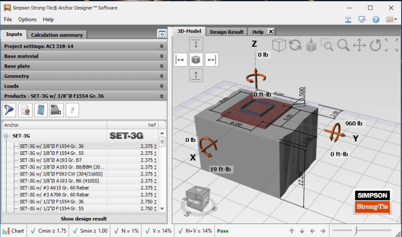
Graph below show result from Simpson anchor bolt calculator. Make sure you have adequate edge distance and embedment depth. I assume you have reinforcement to prevent tension pull out, but not for shear.

image_bvvvn7.png
 
JLNJ - yes you are right,the failure mode is concrete breakout so I guess I am going to submit the report as is to EOR, with my numbers and they have to confirm slab design on their end..

 
retired13 - thanks a lot for taking the time to check it. I didn't know they have their own software. Will look into that
 
Yeah, I think it's the spacing also. You probably want to consider supplementary reinforcing here for a few reasons, even if it requires longer anchor lengths to develop the lap you need.

----
just call me Lo.
 
Retired13:
Isn’t the correct bolt tension (19ft-kips)(12 “/ft)/(5” x 2 bolts) = 22.8k/bolt?
 
retired13 - the shear should be 6000 pounds, not 960, and the moment should be 19000 ft-lbs not 19 ft-lbs. Big difference.

Heldbaum - you are going to need something like a 6'x6'x18" footing to resist the overturning. No way a thin slab works here.

Maybe you can get an 8"x8" bolt pattern to work, but the base plate is going to be thick and the embedment deep.

You might be able to bargain the sizes down a little by using a load factor of 1.0 (instead of 1.6 typical for a live load) using the "extraordinary event" provisions.
 
Yes, I missed that 12 factor :) Thanks for the sanity check.

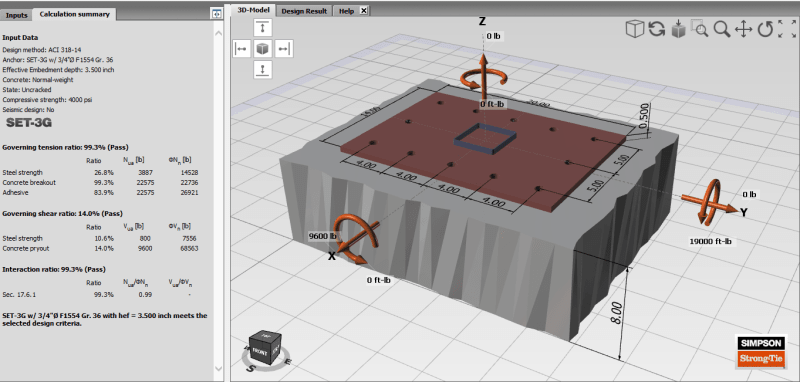
The revised layout. Note, concrete breakout controls the design. I will do a hand calculation in order to better utilize the reinforcing steel. The Simpson design tool is free for download.

image_snj05p.png
 
JLNJ, Thanks for noticing and report the mistake.

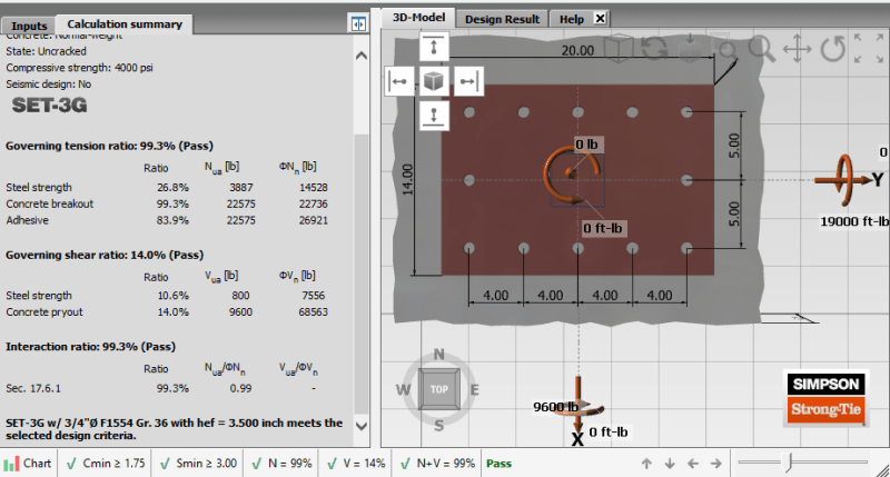
Top view.

image_ljeifk.png
 
Hello, so I ended up designing the plate for working loads of 6 kips without SF considering extraordinary conditions as JLNJ suggested (bending moment 12 k-ft). EOR gave me his blessing. I ended up with 1/2x8x16 plate with (6) - 1/2" epoxy anchors with 5" embed.
Thank you everyone for help, I appreciate it as always.
 
Status
Not open for further replies.

Part and Inventory Search

Sponsor