Eng-Tips is the largest engineering community on the Internet

Intelligent Work Forums for Engineering Professionals

  • Congratulations waross on being selected by the Tek-Tips community for having the most helpful posts in the forums last week. Way to Go!

Hand calculations vs FEM analysis huge difference 4

Status
Not open for further replies.

JM_10

Industrial
Nov 30, 2017
17
0
0
DE
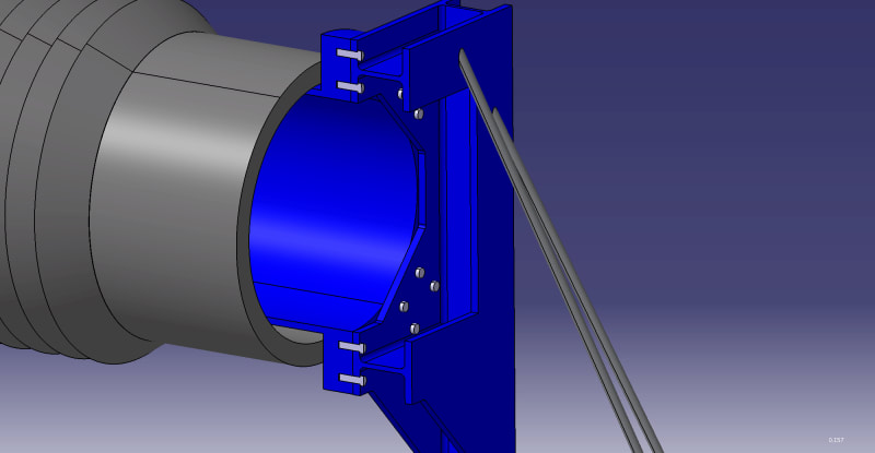
So I am designing some steel structure where exists a bolted joint
Overview_pxcytk.jpg


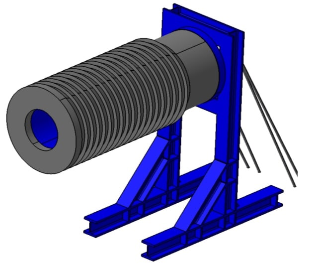
The "cylinder" (total 11 tons), is joint by 20 bolts (M22 10.9 grade bolts) to the "frame" or beams (S275 steel, HE 180M profiles).

20Bolts_setup_kq0pwe.jpg


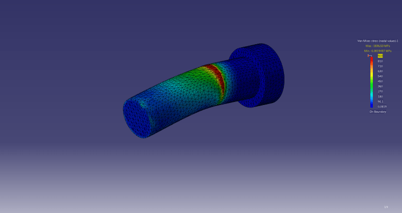
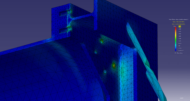
The FEM simulation is predicting high Von Mises stress in the joints holes and the bolts themselfs

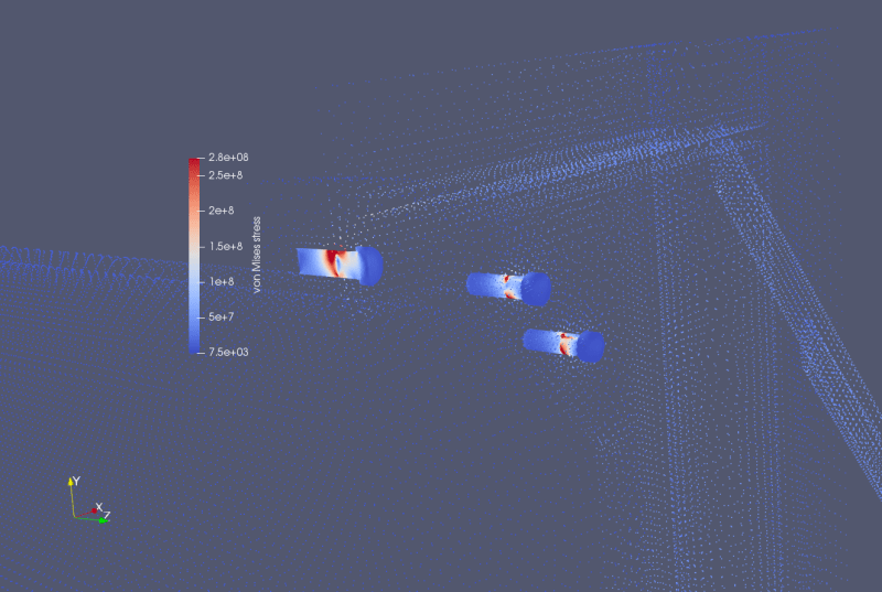
I have used two softwares: Catia v5 using virtual bolts and Simscale using actual 3D bolts (bonded contact)

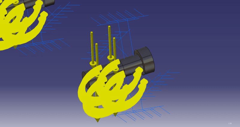
Catia: (virtual bond)
7.2_Catia_ndp9xc.png


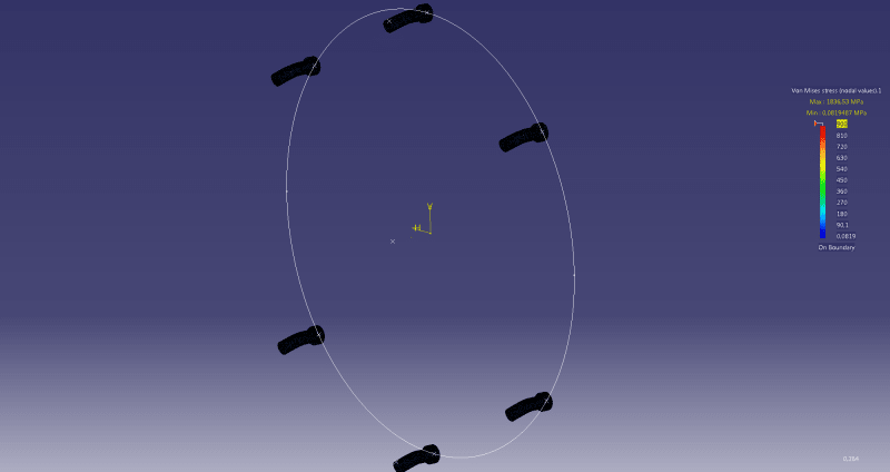
Simscale (bolt in CAD). Here, max VM is 1880 MPa!
7.1_MAX_1880_2_yijlz4.png


However, I made some calculations following Eurocode 3, and the results are it is safe even using only 2 bolts:

I calculate the "Ed" values like this: I am assuming only using 2 bolts (conservative side)

Bolt_Tension_h4fod7.png

Bolt_shear_uaokux.png


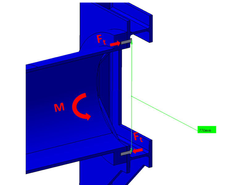
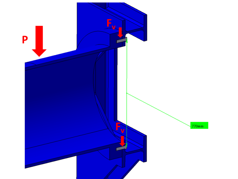
So then each bolt is suffering some tension force Ft and Shear force Fv. Easy to get

Then, I follow the technical code:


Untitled_ollvdj.png


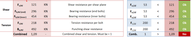
Rd values (resistance) are higher than the actual Ed values. Just "Combination" is >1, but it´s pretty close, and you have to consider my structure has 20 bolts, no 2

Do you have any thoughts why is the FEM predicting so high stress in the area?

Thank you,
regards
 
Replies continue below

Recommended for you

Do you have any thoughts why is the FEM predicting so high stress in the area?

Most likely it is due to stress concentrations. If the system isn't subjected to fatigue loading I would forget about them. (Especially if it is working by code.)

You can model all sorts of things (that work by code).....but there will be stress concentrations that will exceed allowable(s). For homogenous materials (like steel) under static loading....these concentration(s) are (typically) ignored.
 
you have 2 bolts top and bttm CL and patterns of 4 bolts at the 45deg (60deg?) locations ... I'd've put 4 bolts on the CL as well (6 patterns of 4 bolts in all).

I don't know simscale but I'd be suspicious of CATIA FEA ... I think the software is very limited in what it can do, and most people using it are not trained (IMHO) in FEA.

Your stress peaks are probably due to some constraint in the model. Also note these stresses probably exist in the real structures too, just undetected (very localised).

another day in paradise, or is paradise one day closer ?
 
The reality of connection design often differs greatly from how we approach an FEM analysis. The code provisions often assume a certain degree of localized yielding will occur in a properly functioning connection.

That's what the FEM analysis will show. But, when it occurs over such a small area, it can usually be ignored.... based on your engineering judgment. I say that not to dismiss these stress riser. But, rather to emphasize the that to dismiss it, your engineering judgment needs to understand the intended behavior of the connection parts, and how much localized yielding can occur, what the ramifications of it can be, differences between ductile and non-ductile failure, et cetera.

I think if you pull open code commentaries and text books and such, you will a good amount of information about localized yielding and deformation of the base material in bearing around a bolt.

I don't recall seeing the same sort of thing with the bolts themselves. But, the codes usually talk about the total force in the bolt, not localized stresses. So, I don't think this is something that they're really looking at. Unless you have some weird bolt demand forces (other than regular shear and tension) then I don't know if FEM stresses in a bolt will really tell us much useful information.
 
@DenverStruct You are right, thanks for the information. I realized I need some inputs about how FEM mesh is working, that article has been useful!

So thank you all for your answers. All of them have been useful

I will redo the meshing process with detailed analysis attending mesh convergence. First, I will start by doing individual parts analysis to find out the optimal mesh size. Also I will fillet every 90º edge


On the other hand maybe you can tell me your thoughts in this:

I also run some individual simulation of 6 bolts, clamped in its surface in contact to the beam, and moment + force applied in the cantilever surface, like this:

6_Bolts_test3_ku2fr7.png


6_Bolts_test_naurqu.png


I made this in order to find out the reactions in each clamp support

That way I could try to estimate the tension force "Ft Ed" and shear force "Fv Ed" each bolt is suffering. Results happen to be very similar to what I predicted by hand calculations (Using equilibrium and proportional equations).

But, stresses are again too much high (1800 MPa!):

6_Bolts_test2_wwgeqs.png


At this point one can not blame this to singularities due to sharp corner, because there are not

If I look at clamp support reactions in FEM results, I can see obviously the Force reactions, but also Moment reactions in each bolt of value around 22 KNm in both x and y axis (z is the axis normal to bolt section).

Maybe I am missing some external forces in by hand calculations? (apart from "Fv Ed" and "Ft Ed"). Code only is considering this two possible external applied forces, no moments


Do you know how should I deal with this?


Edit: Ok I have just tried this: Same simulation but erasing the external moment applied. Only Vertical force
Even that, stress are 970 Mpa in FEM results (Each bolt is resisting ONLY 18 KN vertical shear force). Code predicts a resistance of 121 KN with these bolts. This makes me think Catia FEM is somehow not so accurate...
 
part of your problem could be the constraints.

certainly a big part of your problem is a linear analysis (predicting non-linear stresses).

I assume you're creating detail FEMs of bolts just for the experience ? I mean bolts have allowable shear, tension and bending, and combining these is "QED".

another day in paradise, or is paradise one day closer ?
 
But, stresses are again too much high (1800 MPa!):

At this point one can not blame this to singularities due to sharp corner, because there are not

Shear (and other stresses) are often not linear across a member's cross section. Your contour plot scale tops out at about 900 MPa [in red]....but you are calling out 1800 as a max. You may want to look and see how wide spread that 1800 is.

Do you know how should I deal with this?

To tell you the truth, all I have seen so far, I'd knock out with hand calculations. (With the exception of the figuring the member forces of that frame.)

 
if each bolt is reacting 18kN *6 (or whatever number of bolts) better be the applied shear load ... as the bolts are the only loadpath (yes?) or have you "glued" the faces together ??

I personally don't like CATIA FEA ... I'm not saying it's "wrong" but I think the options available to you (as in how to constrain the model) are limited.

another day in paradise, or is paradise one day closer ?
 
The problem with your model is that you let the bolt flex. In reality, the bolt will be threaded into the connected part. So it should not be able to bend. It has been a while since I use a 3D FEA software. Isn't there a constraint you can add that specify the bolt is always straight?
 
I should go EN 1993 way but I would perform some kind of fatigue analysis or take a bit more conservative safety factor values ate least for shear (EN 1993 goes against ultimate strength)
 
JM_10,

Have you done your due diligence by checking the sum of reaction forces and moments in your load cases?
Usually when I have engineers with very large differences between hand calcs and FEA, there is a problem with the model loadings.

Is your model accounting for pretension and friction between your assembly and the support frame?
Do your assumptions about bolt shear in the code and your hand calculations match the loading as applied in the models?
If your hand calculations and code assume vertical force is taken by friction between the flange and your test stand, the bending in your bolts will go away.

Just some suggestions, your differences seem to large to be easily explained away, I think you should take a critical look at your loadings and how your model is acting vs the assumptions made in code and hand calculations.
 
part of your problem could be the constraints.

certainly a big part of your problem is a linear analysis (predicting non-linear stresses).

I assume you're creating detail FEMs of bolts just for the experience ? I mean bolts have allowable shear, tension and bending, and combining these is "QED".

Hmm ok I will try to have some inputs about non liner analysis too

About the bolts, yes I know about combining allowable resistance. It is in EN 1993,but it only considers sear + tension. Bending is not considered in bolts. Maybe I am missing that

if each bolt is reacting 18kN *6 (or whatever number of bolts) better be the applied shear load ... as the bolts are the only loadpath (yes?) or have you "glued" the faces together ??

I personally don't like CATIA FEA ... I'm not saying it's "wrong" but I think the options available to you (as in how to constrain the model) are limited.

Yes, bolts are the only loadpath as faces are not glued

The problem with your model is that you let the bolt flex. In reality, the bolt will be threaded into the connected part. So it should not be able to bend. It has been a while since I use a 3D FEA software. Isn't there a constraint you can add that specify the bolt is always straight?

Ok that´s a good point. However as far as I know Catia does not have this constraint...

Have you done your due diligence by checking the sum of reaction forces and moments in your load cases?
Usually when I have engineers with very large differences between hand calcs and FEA, there is a problem with the model loadings.

Is your model accounting for pretension and friction between your assembly and the support frame?
Do your assumptions about bolt shear in the code and your hand calculations match the loading as applied in the models?
If your hand calculations and code assume vertical force is taken by friction between the flange and your test stand, the bending in your bolts will go away.

Just some suggestions, your differences seem to large to be easily explained away, I think you should take a critical look at your loadings and how your model is acting vs the assumptions made in code and hand calculations.

Yes, the sum of the 4 reactions match equilibrium. (Forces, only. I will check moments too)

No pretension (only 0,1 KN per bolt) or friction. So it´s even worse the stress

I will review the model assumptions. You can see some overview on the pictures. Hand calculations even assume more loading (cause it´s only 2 bolts)
 
"No pretension (only 0,1 KN per bolt) or friction. So it´s even worse the stress" ... review this assumption ...

1) do you ever like to see slack bolts ? what do you do when you see a slack bolt ? (tighten it) gapping joints are tolerated at peak (ultimate design) loads but not expected at normal operating loads.

2) bolt preload allows the joint to carry the load, particularly the moment, and the shear.

another day in paradise, or is paradise one day closer ?
 
@rb1957

Of course, I think my assumption was not clear

I mean that I run the simulations with no pretension

Meaning that results are not even realistic. When I put some pretension, stress will be much higher in simulations


ok, but I wouldn't expect so; if you include modelling the contact of the clamped up faces.

another day in paradise, or is paradise one day closer ?
 
Status
Not open for further replies.
Back
Top