Continue to Site

Eng-Tips is the largest engineering community on the Internet

Intelligent Work Forums for Engineering Professionals

  • Congratulations KootK on being selected by the Eng-Tips community for having the most helpful posts in the forums last week. Way to Go!

Hanging platform to structural beam connection 3

Status
Not open for further replies.

MFJewell

Mechanical
Mar 2, 2017
366
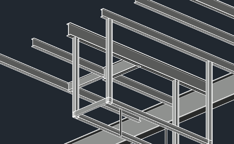
I am looking at adding a work platform for some control valves at one of our facilities. After several iterations, I am going with a hanging platform that is supported by existing structural steel roof beams. This appears to be the best solution based on congestion in the area. That said, I am undecided on welding the vertical supports or using a bolted connection to attach the vertical supports to the W12/W16. The vertical supports are W6 beams that I plan to attach to the bottom flange of the existing beams. Most of the reference material I have covers beam to beam connections using the web and then beam to column connections using the flanges. Anyone have any insight or advice for this particular application.
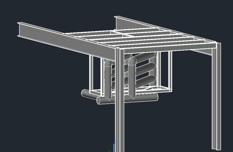
Model_1_wtwgzv.png

Model_2_kituhv.png

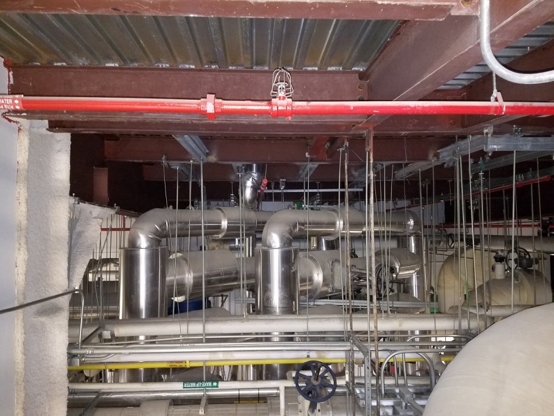
Existing_Beams_igny59.jpg
 
Replies continue below

Recommended for you

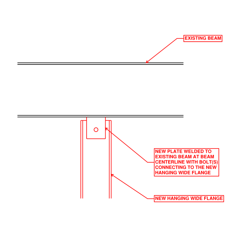
I would do something like the image below.

In addition to this, you need to:
[ol 1]
[li]evaluate the reserve capacity in the existing beams you're attaching to[/li]
[li]verify the new beams/hangers are capable of withstanding the loads that are going to be applied to them[/li]
[li]determine the size of the plate/weld/bolt(s) required for the connections[/li]
[li]provide some sort of lateral bracing to prevent this from moving during use and during any seismic event[/li]
[/ol]


connection_mldswm.png
 
DETstru said:
In addition to this, you need to:
1.evaluate the reserve capacity in the existing beams you're attaching to
2.verify the new beams/hangers are capable of withstanding the loads that are going to be applied to them
3.determine the size of the plate/weld/bolt(s) required for the connections
4.provide some sort of lateral bracing to prevent this from moving during use and during any seismic event


Appreciate the response:

1: I have the original drawings and plan to review loading in more detail. The main beams (W30x108) carry the roof load. There is a packaged cooling tower on the roof which sits on the W16s. My initial review shows that there should be no issue with the additional loading.
2. Already verified. Deflection and stress are well within safe limits. These platforms are each ~ 6 sq feet. They are for a single I&C tech to work on the actuators. Actual load is very low.
3. Currently plan to use .625" bolts for connections.
4. I plan to include some diagonals for bracing, but they are not reflected in my model yet.
 
If you are welding to a (loaded) existing beam.....you will need to evaluate the existing beam as if a portion of it is not there. (Since it will be heated during the process.) It may be better to just bolt it to the existing beam.

 
Correct. The two options I am considering are welding or punching holes in the bottom flange of the existing beam and bolting through it. However, all my reference material on bolted connections doesn't cover that type of connection in tension loading. I believe it is a straight forward case to evaluate, just looking for anyone that has more experience than me.

 
MFJewell, I would weld to the existing beam as I drew it. Welding parallel to the beam isn't much of an issue.
 
However, all my reference material on bolted connections doesn't cover that type of connection in tension loading. I believe it is a straight forward case to evaluate, just looking for anyone that has more experience than me.

You'd generally use a piece of a WT and bolt (on gauge) with the bottom flange above. Prying action would need to be checked. (AISC's manual has equations for that.)
 
WT or double angle connection with prying as recommended by WARose would be my first choice. If the numbers don't support that, my next stop would be DETstru's suggestion which is obviously more robust.

I like to debate structural engineering theory -- a lot. If I challenge you on something, know that I'm doing so because I respect your opinion enough to either change it or adopt it.
 
In that environment I would want to investigate clamp connectors. Welding and/or bolting up there presents some problems which I would rather avoid. If you fabricate the hangers with top plates, you can clamp the plates to the beam flanges.
 
hokie66 said:
In that environment I would want to investigate clamp connectors. Welding and/or bolting up there presents some problems which I would rather avoid. If you fabricate the hangers with top plates, you can clamp the plates to the beam flanges.

Hmm, can't say I have seen those in practice. Any manufacturers you know of that provide something for this application?

Edit: Looks like Kee Klamp (or an affiliated company) have something that might work. They offer BeamClamp BL Flange Clamp. Need to do some research on this option.
 
Hmm, can't say I have seen those in practice. Any manufacturers you know of that provide something for this application?

I think Lindapter still does. Their website:
And that is a good point hokie raises: whatever you do, be sure the manufacturer allows it in that area. I've worked with people where you can't do any cutting in certain areas (let alone welding).
 
Someone might've already mentioned this, but in the event you go with your original connection, or any other connection that also includes field welding, I would specify continuous inspection of the weld due to how critical it will be for your load path.
 
WARose has it. Lindapter would be my first choice.
 
Anyone ever tried the Lindapter units that hold against gravity load using friction from pretensioned bolts rather than any positive mechanical connection?

Look at a few of the pictures for this one.


It makes me slightly nervous, but would also be wonderful to have a rated item that can be used in this application for low load supports for piping or electrical utilities.
 
I haven't used them for shear loading, but have used them for crossing beams, and also for hangers, as in the OP's situation. There are a lot of different types, and I can't remember specifically which ones I used.
 
Hey MEFJewell,

Depending on the type of flexibility you want to have in your piping you should probably go with clipped connections such as what KootK recommended, Since you don't want to create eccentric forces on your roof beams. Usually allow flexibility in the lateral directions while theoretically only supporting the pipe vertically. For DETstru's solution you can use some lifting lug analyses for this type of situation.

If you use clips that Warose helped you out with you are going to have to detail it pretty good because it would require a funky plate size. I wouldn't do it honestly in that situation. I've seen railroad beams tied down with those types of clips but the beams have a very stiff surface to bear on.

Industry standard - PIP - Galvanized A325 bolts. Also use more than one bolt per faying surface. OSHA and AISC both specify atleast 2 bolts for all steel to steel connections. Also, Consider overhead welding being difficult and expensive. The minimum center to center distance between bolt holes is 2.67*nominal diameter. Also, make sure you do a tension and block analysis on the connection. Check your bolt strength for a 5/8" diameter bolt. If you are using modeling software make sure you set supports as pinned.
 
Leftwow, do you mean the existing piping that has hangers connected to the ceiling beams?

These platforms will not connect to or support piping in any way. They are only for a technician to work from when servicing the control valves. Due to the congested area, we are spending $8,000 plus on scaffolding every time they need service.
 
Oh I assumed they were pipe supports my apologies. You have live loads then.
 
MFJewell said:
I am considering... welding...

Actual load is very low...only for a technician to work from when servicing the control valves.

...looking for anyone that has more experience than me.

1. Use welded lugs in accordance with DETstru's suggestion. Specify that attaching the lugs be performed by a welder certified for structural overhead welding.

2. For the overhead welding, require continuous inspection per Nor Cal SE's suggestion.

3. Design each (6 ft[sup]2[/sup]?) platform for live load of at least 1000 lb. or 100 lb/ft[sup]2[/sup], whichever is greater.

4. Design each of the (4?) hangers supporting a platform to support far more than 1/4 of the total load.

Don't want to send unsuspecting workers (fellow employees, in my case) onto a suspended platform... with their (heavy) tools... and perhaps (heavy) replacement valves, etc. This is not a time for a "minimum" or "cheap" design.

[idea]
[r2d2]
 
SlideRuleEra said:
3. Design each (6 ft2?) platform for live load of at least 1000 lb. or 100 lb/ft2, whichever is greater.

4. Design each of the (4?) hangers supporting a platform to support far more than 1/4 of the total load.

Don't want to send unsuspecting workers (fellow employees, in my case) onto a suspended platform... with their (heavy) tools... and perhaps (heavy) replacement valves, etc. This is not a time for a "minimum" or "cheap" design.

3. I used 1000 pounds for my design load.
4. Each hanger (5 total) is capable of supporting significantly more than 1/4 load. I put a lot of safety factor into any platform I design. I keep stresses and deflections very low (since I know that maintenance guys will inevitably use these platforms for more than what the should have been designed for). Usually I target a single support being capable of the carrying the entire load.

That said, I looked at the loading on the roof beams in more detail and it is a little closer than I like. I am currently evaluating supporting it from the floor and may go that route instead ( it will end up cantilevered, but should be a safer overall design).
 
Status
Not open for further replies.

Part and Inventory Search

Sponsor