Continue to Site

Eng-Tips is the largest engineering community on the Internet

Intelligent Work Forums for Engineering Professionals

  • Congratulations SSS148 on being selected by the Eng-Tips community for having the most helpful posts in the forums last week. Way to Go!

Heat Dissipation - Cut Heat Sinks into Enclosure

Status
Not open for further replies.

DesignDad

Mechanical
Apr 26, 2017
11
Hello all,

First time post, long time reader.

I am designing IP65 Electrical Enclosure with 80w internal Heat load. It is small and dont have a lot of room for vents, the only IP65 vents I see are made for large off the shelf enclosures.

I have 2 questions:

1. What is the external solar load I need to consider?
Based on charts below, aluminum enclosure, clear anodized, with 20deg delta T between ambient and internal, should not have a solar heat gain. Correct?​

2. Calculate Internal Air temp with fan, inside of sealed enclosure?
What is the best way to calculate cooling effects in a sealed, small enclosure(12in x 8in x 6in )​
Most of the cooling effect comes from the temperature differential but I want to quantify the air movement effects and if increasing the fan flow rate would improve cooling 20-30%​

See my Calculation Page as an attached file, it is based on surface area of the enclosure, plus the additional area of the fins that are cut into the side.

See also, the box geometry here,
Current Calc Sheet that I have going
Heat_Calcs_iiqnzg.png


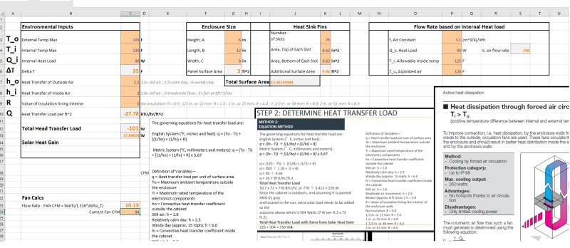
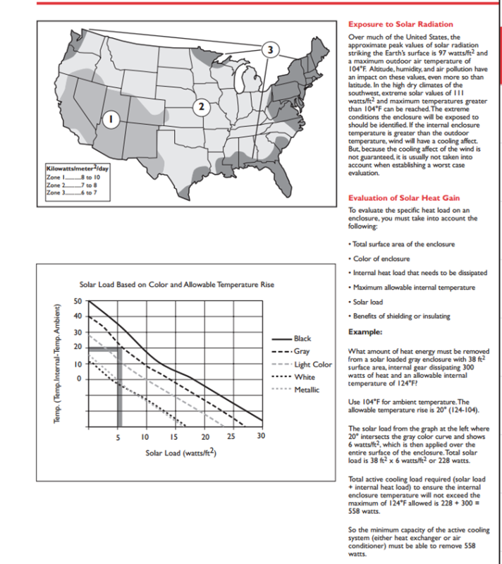
Chart for Solar Heat Gain
Solar_Load_nbg6i8.png


Thanks for all of the help!


Replies continue below

Recommended for you

It appears that you have a funny character in the file name of the second file, making it inaccessible.

Your calculations don't make sense to me. You seem to have jumped to the deltaT as the heat load, yet you do not show how you got there from the actual heat load of 80W.

Your above statement about no solar load also makes no sense.

TTFN (ta ta for now)
I can do absolutely anything. I'm an expert! faq731-376 forum1529 Entire Forum list
 
I can't speak to the solar loading but I did run some quick calculations for your deltaT.

An enclosure of 12" x 8" x 6" (LxWxH) that dissipates 80W using only natural convection will have an outer surface temperature that is about 53C above ambient. If you had enough fins on the sides to approximately double the total surface area of the enclosure you still have an outer surface temperature about 40C above ambient.

I can only get the outer surface temperature for this quick 1st order calculation but your internal air temp will be higher and any component temps will be higher still(possibly much higher).

Any increase in deltaT due to solar loading will be in addition to the numbers I gave.
 
Thanks IRStuff for the reponse

See here for the drawing of enclosure, or the attachment link below.
1. Jumped to delta T as the heat load but dont show how I got there from actual heat load of 80w
- I was using delta T and the surface area to ascertain the amount of passive cooling possible.
- I think I see your point, it looks like I need to take the calculated heat transfer load from the enclosure and add the 80w internal. That will be the amount of heat load that needs to be dissipated.

2. No Solar Load statement.

- This was based on the hoffman enclosure design guide, as well as pentair design guide. The quick reference chart gives solar heat load per unit area(w/ft^2)of different materials(and finishes) based on temperature differences between ambient and max temp of internal electronic ratings.
- See here for reference,hoffman guide:
3. If the heat load is 80w internal and the enclosure adds another 100w. Then what fan/airflow will I need to keep the electronics under 131F(55C). I was thinking of adding a few of the small ip65 vents but they won't add very much airflow.

 
hendersdc said:
An enclosure of 12" x 8" x 6" (LxWxH) that dissipates 80W using only natural convection will have an outer surface temperature that is about 53C above ambient. If you had enough fins on the sides to approximately double the total surface area of the enclosure you still have an outer surface temperature about 40C above ambient.

I can only get the outer surface temperature for this quick 1st order calculation but your internal air temp will be higher and any component temps will be higher still(possibly much higher).

Any increase in deltaT due to solar loading will be in addition to the numbers I gave.

Thanks Hendersdc,

What about natural convection with 84 CFM internal forced air flow(closed loop)? Will this just ensure the temps are more uniform, or will this add to the cooling?

 
It's a very tiny box to be dumping so much power. Assuming that it's coming from a 12x8 board, even forced convection on that area alone will result in 65C temperature rise. If you thermally tie to board directly to your fins, you might stand a better chance.

2> The Hoffman document describes exactly what's been discussed here, which is to add the solar load to the internal load. In order to not cook the innards, the enclosure must rid itself of both loads as efficiently as possible.

3> You're going to need a better class of electronics, like industrial grade, which gets you to 85C typically. My estimate, based on your heatsink area results in a 56C surface temperature. Everything inside must be at a higher temp. Forced convection on the presumptive board area with an htc of 20W/m^2-K results in a 65C rise from the internal air temp. For example, a 4 in^2 aluminum thermal pad, 1-in thick, will only have a 3.3C temperature drop with 80W flowing through it.

TTFN (ta ta for now)
I can do absolutely anything. I'm an expert! faq731-376 forum1529 Entire Forum list
 
IRstuff said:
It's a very tiny box to be dumping so much power. Assuming that it's coming from a 12x8 board, even forced convection on that area alone will result in 65C temperature rise. If you thermally tie to board directly to your fins, you might stand a better chance.


2> The Hoffman document describes exactly what's been discussed here, which is to add the solar load to the internal load. In order to not cook the innards, the enclosure must rid itself of both loads as efficiently as possible.

3> You're going to need a better class of electronics, like industrial grade, which gets you to 85C typically. My estimate, based on your heatsink area results in a 56C surface temperature. Everything inside must be at a higher temp. Forced convection on the presumptive board area with an htc of 20W/m^2-K results in a 65C rise from the internal air temp. For example, a 4 in^2 aluminum thermal pad, 1-in thick, will only have a 3.3C temperature drop with 80W flowing through it.


Thanks for pointing me in the right direction, it looks like I will need liquid cooling or force the electrical engineers to go up in component ratings. The only issue is that there is a legacy electrical component that must be used.

Just to clarify and further my understanding,

I understand the size and limitation on surface area creates limitations on thermal loss. I just thought the more surface area with the fins would be enough for cooling. What equations should I change on my excel sheet that I attached?

from #2 above
- The Hoffman document says that if there is a temperature differential of 20 deg, and it is unpainted aluminum, there should be no heat load from solar exposure. See the graph with lines, what am I missing? The temp diff between ambient and internal will be different?

From # 3
- so forced air flow will help but my surface area limits the ability? I assume applying thermal paste to an inner wall will help conduct the heat out as well. I would also put a fan on that inner wall.
- What are the other options for this, potting the system? or closed loop liquid cooling on one plate?


#2 you are completely misreading the document. It states clearly that to achieve the desired 20 degree delta that the 228 W of solar load PLUS the 300 W of gear dissipation or 528 W (apparent typo of "558 W" in the document) needs to be removed by the "active cooling system."

The 20 degree differential is only between the outer surface of the box and the outside ambient air. You still need to get the heat from the board through the air inside the box to the inside surface of the box. I typically assume two serial convective processes. With a 20 W/m^2-K convection coefficient and 96 in^2 board, that board will be 64.6 degC higher than the internal air temperature.

Unless the internal surface of the box is pin finned, the surface area is limited, so you'd expect at least 18 degC drop from the internal air to the inside surface of the box, but only because you could assume forced convection inside. That puts the board at about 102 degC above external ambient temperature, so that's a non-starter unless you've got extended temperature industrial parts rated for 150 degC.

You could possibly thermal strap the board hotspots to the inside surface of the box as another alternative.

TTFN (ta ta for now)
I can do absolutely anything. I'm an expert! faq731-376 forum1529 Entire Forum list
 
IRStuff,

Thanks for the heads up on double post, I thought that there might be some ideas from electrical engineers in the enclosure thread. If it is against the forum rules for double post, I will remove the one I just added in electrical engineers.

On the hoffman document, I am reading the example on the right hand side. Giving a grey panel with different internal and external temps. Now if you replace that example with aluminum, the same graph shows no solar heat load. Maybe I am just a** backwards on this one. Any help is much appreciated.


Here is the assembly internals, [URL unfurl="true"]https://res.cloudinary.com/engineering-com/image/upload/v1493263228/tips/Milled_Enclosure_gghevv.bmp[/url]

Thanks again
 
I think the issue is that you erroneously assume that what they refer to as "metallic" is what you have, which is not the case. "Metallic" in their example is something that has a mirror finish, like polished chrome. Brushed aluminum has a reflectivity of around 50%, unless you have polished aluminum, will not last in an outdoor environment for very long.

TTFN (ta ta for now)
I can do absolutely anything. I'm an expert! faq731-376 forum1529 Entire Forum list
 
IRSTUFF said:
I think the issue is that you erroneously assume that what they refer to as "metallic" is what you have, which is not the case. "Metallic" in their example is something that has a mirror finish, like polished chrome. Brushed aluminum has a reflectivity of around 50%, unless you have polished aluminum, will not last in an outdoor environment for very long.

No where in the literature does it mention a polished metal. They are comparing the different coatings that can be applied to an enclosure. That is why white is listed under metallic. So if I paint the enclosure white, it will reflect more energy.

When they speak of metallic finish, they are not talking about a mirror finish, polished like a telescope. At least there is no mention of it anywhere.

This is something the guys in the electrical enclosure threads would probably clear up since they use hoffman for everything. Am I allowed to post a specific question about the hoffman document over there, or do you consider that a double post.
 
DesignDad,

I am afraid that the numbers I gave are for the external surface temperature only, even with zero temperature rise through the enclosure wall thickness and perfect coupling of your hot components to the enclosure using thermal grease they are the absolute lower bound of temperature rise using only natural convection for cooling. In reality you will have additional temp rise from the enclosure wall, thermal grease resistance, and the junction to case resistance of your components. No amount of internal air circulation will get below those numbers.

Some things you can do to improve performance are:

- Increase the size of the box and fins
- Actively cool the inside of the box such as:
- Using a Peltier cooler​
- By circulating external ambient air through the unit. This is the easiest and lowest cost route but you will need to drop the IP65 requirement. 63 is relatively easy, 64 starts to push it.​
- Heat exchangers and refrigerant​
- Buy industrial grade components with higher junction temperature limits
- Redesign with more efficient components so you won't be rejecting as much heat
- Reduce performance of unit when temp gets too high until it cools down

As far as the surface finish discussion goes, I agree with IRStuff, metallic refers to a very reflective (high polish) surface.
 
hendersdc said:
Some things you can do to improve performance are:

- Increase the size of the box and fins
- Actively cool the inside of the box such as:
- Using a Peltier cooler
- By circulating external ambient air through the unit. This is the easiest and lowest cost route but you will need to drop the IP65 requirement. 63 is relatively easy, 64 starts to push it.
- Heat exchangers and refrigerant
- Buy industrial grade components with higher junction temperature limits
- Redesign with more efficient components so you won't be rejecting as much heat
- Reduce performance of unit when temp gets too high until it cools down

As far as the surface finish discussion goes, I agree with IRStuff, metallic refers to a very reflective (high polish) surface.

Thanks for the follow up and clarification on the hoffman document, I will have to agree with you and IRstuff on the finish if you are both mentioning it. I know the nema 4x STAINLESS panels usually have a polished finish so that is probably what they are comparing.

I guess the white values wouldn't be applicable?

Thanks for the thoughts to improve the situation. The heat is coming from high data transfer rate, so it is hard to get them to change components.

- Increase size of box and fins, I will look into this I just need to know how far off I am on the calculations I provided and where I am going wrong.

- Ambient air External vent, non-ip65 style
--what about these type of vents? You would need more for increased flow, but might work with a nema4 filter?
---
- Peltier Cooler
--- is this hot and cold plate with internal fan over the cold side?

Heat exchanger and refrigerant
-- I need this to be portable, I cant find small systems for this.

Thanks for the help!


Could I use 2 or three of these mounted externally? Maybe I can use conduction from electronics to thermal grease to inner wall the solder and mount this on the external housing with a protective cage/filter around it? to this mounted externally? Then I It takes 130w out,

Is the contact area a limiting factor? SO the 130w is limited to that surface area? If you apply 2 of them to a larger surface area, the cooling rate will decrease?
 
Your linked vent is not for cooling air flow, it is just to equalize pressure and humidity with outside air. You will get essentially zero airflow through them.

From a quick look at your spreadsheet, it looks like your overall heat transfer numbers are close to mine if we use the same inputs.

You will need to change your numbers to reflect worse case which is perfectly still air.

You already have a huge number of very large fins in your spreadsheet, I don't think you will be able to fit as many as you list with your current box size. Changing the box size and fin dimensions in your spreadsheet will let you know how big to make things, just make sure that they make sense. Also, for natural convection you will have the best performance with fins oriented vertically instead of horizontally, I don't know how your spreadsheet takes this into account.

The forced air circulation portion of your spreadsheet doesn't make sense to me. You cannot use the outside ambient air temp as your T_u. T_u is the temp of cooled air within the enclosure and you will be hard pressed to know that number without simulation but the difference between T_u and T_i will be minimal.

In general, when I approach a design like this, I start with a high level spreadsheet analysis (like yours) that only gives me the external surface temp of an enclosure for a given size, power, and ambient temp. This gives me a high level read on where I am on the scale between no way -> cake walk. Usually you end up somewhere in the middle and more analysis is needed which is where you are. Spreadsheets have their limits and it is unlikely that you can put the level of detail I think you need for this design into one.

You will have a few critical components to worry about in your device and I think you will need to do CFD analysis to have confidence in your design.

Yes, a peltier cooler is essentially a cold plate. If it is on the outside of your enclosure you can cool the enclosure while rejecting heat to ambient. If it is inside your enclosure you can cool the whole PCB or selected components while rejecting the heat to the enclosure. They are not very efficient so your whole device power will increase but they are relatively simple and it gives you some options to cool specific things that need it.
 
You could mount those fan sinks externally but they will not meet IP 65 as they require a lot of ambient airflow.

In a sealed case like this it is generally more effective to couple hot components to the enclosure using thermal grease as you suggest vs internal circulating fans if your geometry allows it.
 
Hendersdc,

I agree about the air flow calc area for aspirated air, unless there is serious heat pipes directing the internal air, it would be almost equal.

On my calc sheet, I need to add solar heat gain, any help would be much obliged. Then I would add the solar heat gain with the 80w internal to get my total load needed to dissipate. Last, I will look at the heat transfer load to see what the enclosure can dissipate through natural convection. The internal fans, are negligible and only help make things uniform.

Idea for maintaining ip65 rating would be to create a box with 2 sections, on sealed and one not. The only passthrough I would need is for dc wires and I can use the waterproof gland for that. The fan can be replaced with an IP67 fan and just have a sheet metal cage/filter around it.

Ok so my options as I see them

1. Passive cooling, Increase enclosure surface area(more fins internal and external) and mount hotspots on internal wall. Internal fan will help but not drastically.
- I am just missing the solar load on my calc sheet and I am unclear on that aspect. Any help is appreciated.
---Will be hard to isolate shock and vibe. Will need external bumpers.

2. Active Cooling, External heatsink/fan/cpu cooler
--Use wire gland and ip67 fan to make it work in rain.


I agree on the CFD, that is what I am used to. Currently using Inventor 2017 and don't have access to CFD program to look at design iterations.


Can't help much on the solar loading, I would just be reading papers on it like you. Another way to look at it would be to just treat it as net radiative heat transfer where you take the incident radiation from the sun and subtract out the radiation from your box to the environment. I am sure that this is the approach your papers take (along with a lot of other considerations like which wavelengths are absorbed by the atmosphere) but this way you can fully see the math behind it. It will be close enough for spreadsheet calcs anyways.
 
IRStuff and Hendersdc,

Thanks for the suggestions thus far!

I think IRstuff has deep knowledge on solar radiation,
I read into the mil standard he mentioned and it was interesting/enlightening.

Just wonder if anyone has that calc sheet that was mentioned on that thread.
 
Status
Not open for further replies.

Part and Inventory Search

Sponsor