Hello All,
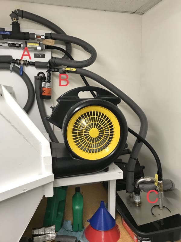
I’m beginning to add new components to our testing system that has been through several upgrades already. This system is designed to test heat exchanger and oil thermostat performance. For the scope of this post, I will be concerned with only the heat exchanger. We use an electric gear pump to move engine oil through SAE -10 ID hoses and fittings. The oil is drawn from a heated reservoir (a cheap food fryer at the moment). The heat exchanger sits within our homemade wind tunnel. A 3-speed radial blower is what moves air through the tunnel.
Once the engine oil is at the temperature that API/SAE uses to rate their viscosities, we set the flow rate with a manual valve (A) and analog flow meter (B). We also set line back-pressure using a manual valve (C) and analog pressure gauge (D). The oil is still being heated by the fryer. It was short-sight how this adjustment would prove to be erroneous which is why we have the oval gear flow meter now. The oil changes viscosity as it gets heated and diffuses heat, and thus changes flow rate(s). The oval gear meter will now accurately record the oil flow rate so that the heat equations and their values don’t become erroneous. Being that the ambient air’s thermophysical properties don’t necessitate precise flow metering, I’m using a bulk average flow rate calculated from another round of testing.

Here’s some more background regarding the evolution of our test system; I’ll make this short. I was part-time here at the company until winter of 2015. We still had this garage way of testing things that I was used to operating as a part-time employee. As a full-time employee, I knew that overalling the testing system was on the docket. Opportunistically for us, my boss’ cousin was laid-off from Cummins so he helped my boss with the project. I provided a lot of literature for wind tunnel design, but had very minimal input on the overall design and component selection/integration. My boss had an idea of what he wanted it to do and they sort of worked on it from there.
Unfortunately, there have been several later upgrades due to the fact that due diligence was not carried out in designing the original system, and/or lack of knowledge regarding testing systems. It’s now up to me (and the financial support of the company) to get this system where it needs to be.
I got down-and-dirty in my roommate’s graduate heat transfer book to refresh my brain from a far more thorough source of information than my undergrad book. I also picked up Compact Heat Exchangers by Kays and London since I needed access to some discrete heat exchanger details.
I had to sell the sh#t out of my intended upgrades to get a few of them approved. I have some of these parts on order or in my possession now: proper line and tank insulation, an oval gear flow meter, as mentioned before, and some extra thermocouples.
I’ve ordered some Armacell pipe and component foam that I will be using to insulate the lines and tank to minimize energy lost to the surroundings.
The other upgrade I got approved were two more thermocouples. I really wanted about nine fore and maybe 20 aft, but that wasn’t in the budget to get a new DAQ for those. Instead I’ll be doing point traversing. The textbook says that they did 9 point traverses fore and 27 point traverses aft of the exchanger. I’m going to try and set it up as 10 and 20 so that it works out better when timing the point traversing in 30 second or 1-minute intervals.
I also wanted to install an electric motor controller for the oil pump and radial fan that’s related to the thermal load of the system and windspeed, along with a truly-capable oil heater. Ideally, I want a fully automatic, non-human input testing system, but those are always pricey.
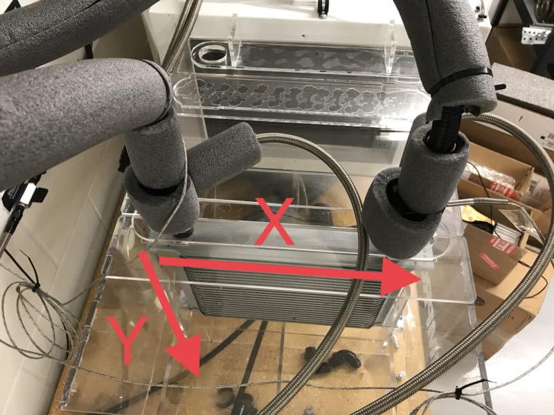
After designing the point traversing apparatuses for the fore and aft positions, I’m wondering how to best carry out the actual traversing. I’m thinking it’s going to be best to start the measurements at the inlet (hot) port. Then at some time interval I will begin moving the thermocouple down the core, as shown. Once I’ve completed all the Y values for that X-point, I’ll move to the next X-point and repeat until the whole heat exchanger has been done, fore and aft.

Does this seem scientific and practical enough to get the best bulk average temperatures for the heat exchanger core? Some of the heat exchangers tested are going to be dual-pass cores; I am wondering if those will need to be treated differently?
I’m beginning to add new components to our testing system that has been through several upgrades already. This system is designed to test heat exchanger and oil thermostat performance. For the scope of this post, I will be concerned with only the heat exchanger. We use an electric gear pump to move engine oil through SAE -10 ID hoses and fittings. The oil is drawn from a heated reservoir (a cheap food fryer at the moment). The heat exchanger sits within our homemade wind tunnel. A 3-speed radial blower is what moves air through the tunnel.
Once the engine oil is at the temperature that API/SAE uses to rate their viscosities, we set the flow rate with a manual valve (A) and analog flow meter (B). We also set line back-pressure using a manual valve (C) and analog pressure gauge (D). The oil is still being heated by the fryer. It was short-sight how this adjustment would prove to be erroneous which is why we have the oval gear flow meter now. The oil changes viscosity as it gets heated and diffuses heat, and thus changes flow rate(s). The oval gear meter will now accurately record the oil flow rate so that the heat equations and their values don’t become erroneous. Being that the ambient air’s thermophysical properties don’t necessitate precise flow metering, I’m using a bulk average flow rate calculated from another round of testing.

Here’s some more background regarding the evolution of our test system; I’ll make this short. I was part-time here at the company until winter of 2015. We still had this garage way of testing things that I was used to operating as a part-time employee. As a full-time employee, I knew that overalling the testing system was on the docket. Opportunistically for us, my boss’ cousin was laid-off from Cummins so he helped my boss with the project. I provided a lot of literature for wind tunnel design, but had very minimal input on the overall design and component selection/integration. My boss had an idea of what he wanted it to do and they sort of worked on it from there.
Unfortunately, there have been several later upgrades due to the fact that due diligence was not carried out in designing the original system, and/or lack of knowledge regarding testing systems. It’s now up to me (and the financial support of the company) to get this system where it needs to be.
I got down-and-dirty in my roommate’s graduate heat transfer book to refresh my brain from a far more thorough source of information than my undergrad book. I also picked up Compact Heat Exchangers by Kays and London since I needed access to some discrete heat exchanger details.
I had to sell the sh#t out of my intended upgrades to get a few of them approved. I have some of these parts on order or in my possession now: proper line and tank insulation, an oval gear flow meter, as mentioned before, and some extra thermocouples.
I’ve ordered some Armacell pipe and component foam that I will be using to insulate the lines and tank to minimize energy lost to the surroundings.
The other upgrade I got approved were two more thermocouples. I really wanted about nine fore and maybe 20 aft, but that wasn’t in the budget to get a new DAQ for those. Instead I’ll be doing point traversing. The textbook says that they did 9 point traverses fore and 27 point traverses aft of the exchanger. I’m going to try and set it up as 10 and 20 so that it works out better when timing the point traversing in 30 second or 1-minute intervals.
I also wanted to install an electric motor controller for the oil pump and radial fan that’s related to the thermal load of the system and windspeed, along with a truly-capable oil heater. Ideally, I want a fully automatic, non-human input testing system, but those are always pricey.
After designing the point traversing apparatuses for the fore and aft positions, I’m wondering how to best carry out the actual traversing. I’m thinking it’s going to be best to start the measurements at the inlet (hot) port. Then at some time interval I will begin moving the thermocouple down the core, as shown. Once I’ve completed all the Y values for that X-point, I’ll move to the next X-point and repeat until the whole heat exchanger has been done, fore and aft.

Does this seem scientific and practical enough to get the best bulk average temperatures for the heat exchanger core? Some of the heat exchangers tested are going to be dual-pass cores; I am wondering if those will need to be treated differently?
