Continue to Site

Eng-Tips is the largest engineering community on the Internet

Intelligent Work Forums for Engineering Professionals

  • Congratulations cowski on being selected by the Eng-Tips community for having the most helpful posts in the forums last week. Way to Go!

Heat Transfer Coefficient Calculation 3

Status
Not open for further replies.

ghost_rider

Mechanical
May 3, 2018
12
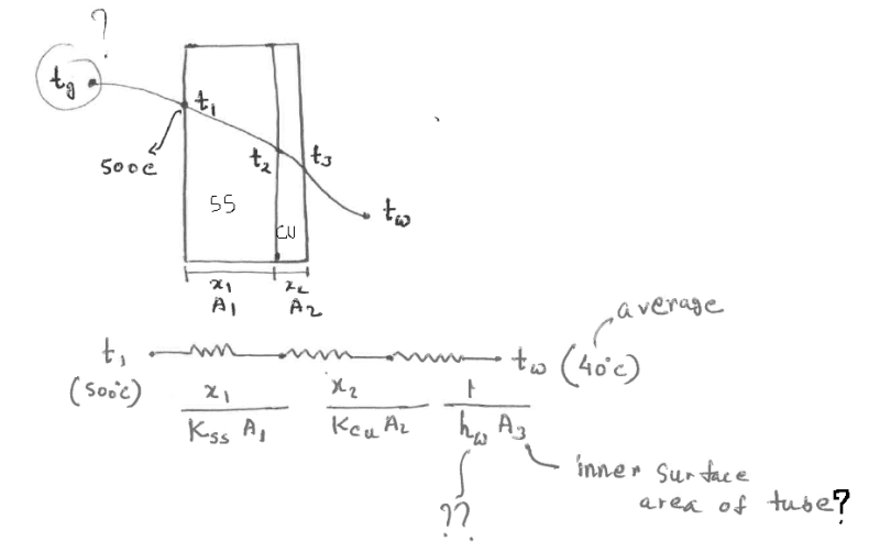
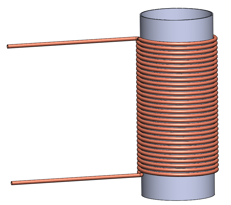
I have a copper coil wrapped around a stainless steel cylinder (please see attached). The temp. of inner surface of the cylinder is assumed to be 500C. Water will flow through the copper coil, entering at 20C and leaving at 60C (therefore the average water temp is 40C).
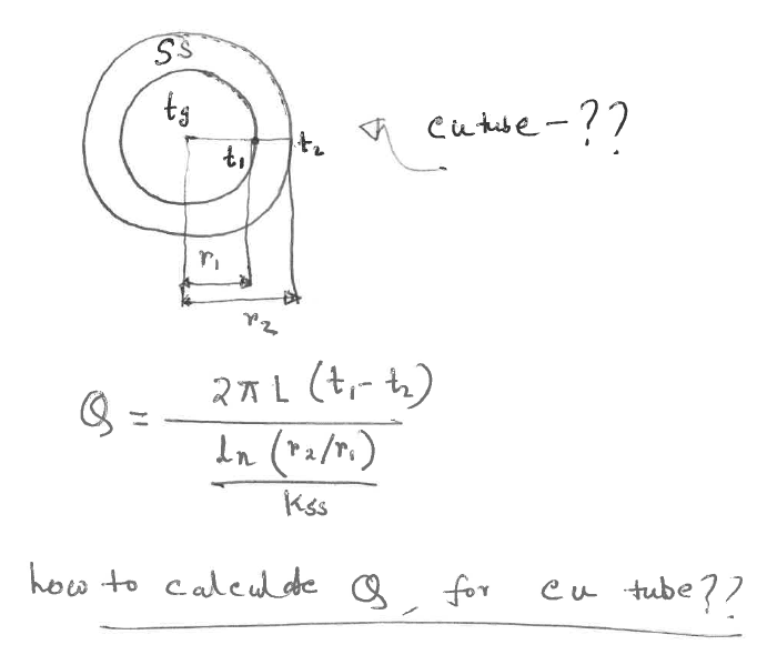
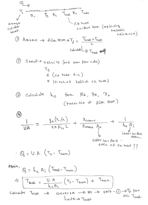
Now for the heat transfer from the coil wall to the water inside, Q=U A dT (W) can be used? I'm having difficulty in calculating U. Here, the area is the surface area of the coil. But, should dT be the difference between coil wall temp and avg. water temp? Before that, can I use same equation to determine heat transfer between cylinder and coil outer surface? Again, I'm having difficulty in U calc.

Once I have Q, I can use it to calculate the water flow rate required to achieve a gradient of 40C (60C-20C) for Q=m(mass flowrate) Cp dT (W)
It will be really helpful if anyone can please advice on U calculation. Also, on the method I have used to get flow rate.

Note: fuel is burnt inside the cylinder. However, to simplify the problem I am assuming the inside wall temp will be 500C.
 
 https://files.engineering.com/getfile.aspx?folder=a5469b2c-022e-4563-9775-12203979f8cf&file=1.png
Replies continue below

Recommended for you

A)What are you proposing to get good contact between the copper tubing OD and the hot SS cylinder? Suggest burying these Cu tubes in a high conductivity cement, like the one used for steam tracer tubing.
Perry Chem Engg handbook gives guidance on the correction factors to be used for helical tubing with the base Dittus Boelter / Sieder Tate equation for the inside htc for the Cu tubing (between the tube ID and water).
B)To be cautious, I would only use say 80% of the Cu tube OD surface area when computing the heat transferred from the SS cylinder to the Cu tube, and coincidentally make some allowance for the fact that not all the Cu tube external surface will be at close to 500degC. A quantified estimate of this mean external surface temp can be made with input of the mean thickness of the conducting cement - so this is a thermal conductivity calc only.
C)Be careful with using water here - a critical calc will be to compute the Cu tube inside ID film temp, which must be estimated to be less than the boiling point of water at the min operating pressure of the flowing water. Else switch out for a higher boiling point coolant -see (E).
D)Purity of the circulating water will also be critical; use inhibited demineralised or DI water to avoid scaling; keep the DI / DM recirculating system expansion drum under N2 blanket.
E)A safe bet to avoid vapor blanketing / vapor lockup in these tubes is to switch out water with some high temperature stabilised hot oil, which could one of the popular Therminol HTFs' or similar mineral oils from ExxonMobil / Shell / Chevron etc. Select the hot oil which has a max continous permitted film temp > the computed max film temp in the Cu tube ID surface.
 
If you have a flame heating a wall, and are going to assume a wall temperature of 500C, why not just jump ahead and assume the final answer? You will be just as accurate.

I cannot add much to George's reply except that such coils are usually attached using the process of furnace brazing. Without doing this your heat transfer coefficient will be at least a factor of 10 lower.
 
Your water is inside the copper tubes, which are wrapped around the (assumed) 500 deg C wall of the cylinder, right?

SO, how are you keeping the water from boiling, or are you assuming the copper pipes ARE pressurized and so are falling into ALL of the pressure vessel and boiler construction laws and certifications? If the wall temperature were much, much less - say 125 or 150 degrees, water could "possibly" be assumed to be in the tubes, even though portions of the tube near the wall are over 100 deg C. But you have a boiler present, multiphase flow and or very high pressure.
 
Many thanks for your the replies with Some really useful suggestions.

The contact between the cylinder and tube is not that good. Therefore, burying the tube is a good suggestion.

I apologise for not mentioning that it is an open loop system for the water flowing through the tubes. That is why, I would like to calculate the flow rate required for the water to reach 60C. Too low flow rate could possibly produce steam and water temp will not reach 60C if too high. It is to get an approximate value of the flow rate, which can be used as the starting point for actively controlling the flow rate since in reality the flame temp. will vary a lot I guess.

I was assuming the following equivalent thermal circuit (It may be incorrect):

Untitled_kanthp.png


However, I am confused if this problem should be treated as the following:

Untitled1_ccfwri.png


But, in this case, how to define the copper tubes?

I haven't done any heat calculations for ages. Therefore, my skills are bit rusty. I wanted to simplify the problem as much as I could. Obviously, there are more accurate ways to do it. However, at the moment I would like to do some basic calculations. I can later do an parametric optimisation to fine tune the design. Any suggestion would be really helpful. Also, is there an easier way to calculate the temperature generated by burning say 1 kg of wood, using its heating value? Thanks in advance.
 
1. Your copper coil CANNOT be a single coil (spring-like winding) around the inner cylinder. It will be physically impossible to get enough water flowing any physically-sized coil around the cylinder to carry enough heat away from the walls to prevent boiling, much less a lower T_water_max of 60 deg C. Now, many parallel copper tubes "might" work, since no single tube will be blocked by a nucleate boiling or a steam bubble under worse-case conditions. . Ultimately, the safest solution is many smaller tubes (to maximize contact area between the OD of the cylinder and OD of the smaller copper tubes, all such tubes running axial from one end of the cylinder to the other. The copper tubes then are piped from a common header below, and bend away from the cylinder and collect into a single header above.

You MUST get away from the theoretical algebra at this point and assume some OD cylinder, wall thickness cylinder, OD copper and wall thickness copper. THEN, and only then, can you calculate the maximum number of tubes running outside the cylinder, THEN the actual contact area of each tube and solder connection to OD of the inner cylinder. 15% to 20% max of cylinder circumference, unless you fill the gap completely with some paste or conductive filler compatible with your solder. Deposit the filler in the length of the gap after soldering with some long hypodermic syringe needle maybe?

You must determine this actual, practical area of effective heat transfer contact before continuing.
 
Thank you for the reply. I have some initial values of the pitch, no. of turns, OD, ID for copper tube. The targeted water temp. can be within 60C to 80C.

Untitled3_nqbso6.png


The contact area is minimal in the above arrangement. My aim is to get some flow rate figures, to achieve that Tmax. If the figure is unrealistic, I can safely conclude that the design is impractical. Further modifications should be made, such as the one you suggested using smaller tubes running axially. Thanks.
 
ghost rider said:
Note: fuel is burnt inside the cylinder. However, to simplify the problem I am assuming the inside wall temp will be 500C.

You are simplifying away some important information.

What fuel, and at what rate?

What happens to the combustion gas, and what temperature is it?

With those two things you at least have a rough idea of how much heat you need to deal with.

Then it's really simple to calculate the water flow required for a reasonableness assessment.
 
For the time being, it is assumed to burn wood and the combustion gases flow upwards. It is a part of a bigger system. I want to extract some of the heat from that combustion gases to heat the water flowing through the copper tubes at a specific temp. Unfortunately,I do not know what temp. the burnt fuel would produce. That is why I assumed a temperature first. It would be useful to develop relationship between the parameters. But, the difficulty I am having is assuming a value for convective heat transfer coefficient between ID of copper tube and water. Also, the copper tube is in partial contact with cylinder OD, and I am bit confused if considering a 50% surface area for in U calculation using the thermal circuit is a valid assumption or not.

My initial heat flow circuit with steady state assumption and adiabatic condition:

conduction from cylinder ID (assumed 500C) to its OD [logarithmic U value should be used for cylinders?]-> cylinder OD to copper tube OD [50% surface area?]-> cu tube OD to cu tube ID -> cu tube ID to water (avg. temp 40C) [struggling with h (w/m2K) value]

Any suggestions would be much appreciated. Thanks.

 
It will be a struggle to keep this water from boiling if you are running this water stream at atmospheric pressure or there abouts. This tube ID film temp is critical.

The Dittus Boelter equation for the tube ID htc to flowing water is N_Nu = 0.023(N_Re^0.8)(N_Pr^0.33) since we can exclude skin viscosity effect correction for water. Presume you know what these terms mean. Properties should be calculated at the film temp, which is the average between tube wall temp and bulk fluid temp. Assume a film temp to get the iterative calcs started.

Off hand, 500degC for combustion flue gas seems rather low, unless you've got loads of excess combustion air.
 
It seems there are couple of assumptions to make: Film temp. and flow velocity for Reynolds number (for Dittus-Boelter eq. it has to be turbulent?). My aim is to find the flow rate at which water would not boil i.e. achieve bulk fluid temp. of say 40C or 80C (this can be impractical to achieve though).

I can get some h values through iteration from Nu, assuming film temp. and flow velocity. However, the problem becomes a bit complex. Any ball park figure for the h value would be sufficient at this stage to come to a conclusion on the system's ability to prevent water from boiling.

500C for ID of cylinder is a crude assumption I had to make. There is a provision for air blow holes. But, I am trying to keep it as simple as possible.

If I can estimate/assume the amount of heat available from combustion, the problem would have been easier to solve I guess. :(
 
You've got all the correlations now. Start with some assumptions, say a good velocity of 4m/sec of water in the Cu tubes ( this also gives you the mass flow of water), then assume some film temp, compute h_w, sum up all the resistances to get an overall UiAi, where Ui is the overall htc with reference to the total inside surface area of the Cu tubes. This gives you the actual Ui and Ai for this system. You could ignore the metallic wall resistances since they would be small ( cyclinder wall, Cu tube wall) in comparison with hi. To your first diagram showing the resistances in series, also include a conservative estimate for the furnace brazing(or conducting cement) in which these Cu tubes are buried.

Approaching this from another angle, Assuming you've set up this up countercurrently (flow of water goes downward to heat up , while flue gas goes upward to cool down), estimate the LMTD, given that you've got water going from 20degC to say 60degC, then apply Ui. Ai . LMTD = MCpdt to get you the required Ui for the actual Ai. Note that the the flue gas temp would cool down by an amount commensurate with the heat pick up by the water, so this helps to get the LMTD.

Adjust the values for Ui, LMTD, Ai till all assumed values match those estimated.

Then finally calculate the worst case film temp, which would be at the hot end of this system ( water exiting in contact with upcoming flue gas). Here we want to calculate the Cu ID wall or tubeskin temp, For this section, compute a local value of U for a small section of Cu tube using the same procedure as above. Get all assumed values to match up with those estimated. Then, finally estimate the tubeskin temp with input from localised value of Q. This is a step by step calc where you first compute the terminal temps across the combustion cylinder wall, then move down to compute the terminal temps across the brazing. End temp at brazing = Cu tubeskin temp. Then you have the estimate for film temp = 0.5 ( tubeskin t + bulk temp at this section). See if this is less than the lowest boiling point of water at this location. If this is not satisfactory, start all over again with higher Cu tubing surface area or increased water flow or both.

Look up your heat transfer text for the formula required to get to overall Ui where you sum all the resistances.


Should be based on the film temp, since this is where the resistance to heat transfer is. If the film temp exceeds the boiling point, then this Dittus B equation wont apply - since this is only for single phase convective heat transfer.
 
I was thinking if direct contact of copper tubes with combustion gases would cause more corrosion, oxidation etc.
 
I have used a conservative approach to calculate the copper tube wall temp. Does this method seem logical? It is an iterative process.
Any suggestion would be helpful. TIA.

calc_r7au5w.png
 
Minor correction at equation 4 : The 2nd term on the RHS could be modified to look like the first term on the RHS with an assumption on the mean average concentric cement thickness around the Cu tube, and then you wouldnt need the A term in the denominator.

Otherwise, you're ready to go with these iterations.
 
Thank you for the correction. I think assuming a concentric conductive cement where the Cu tube is buried makes it easier to calculate U.

As you mentioned earlier, after the converged Twall consequently Tfilm is achieved, if it is higher than the boiling temperature can we say that the current design parameters (tube dimensions, flow rate) does not satisfy the requirement?
 
Yes, Tfilm should be some safe distance away from the boiling point of water at that pressure. As suggested earlier, the highest value for Tfilm would be at the "hot end" of the coil.
 
Status
Not open for further replies.

Part and Inventory Search

Sponsor