Continue to Site

Eng-Tips is the largest engineering community on the Internet

Intelligent Work Forums for Engineering Professionals

  • Congratulations SSS148 on being selected by the Eng-Tips community for having the most helpful posts in the forums last week. Way to Go!

Height Adjustable Stand shelf

Status
Not open for further replies.

var10

Mechanical
Apr 4, 2013
188
Hello All,

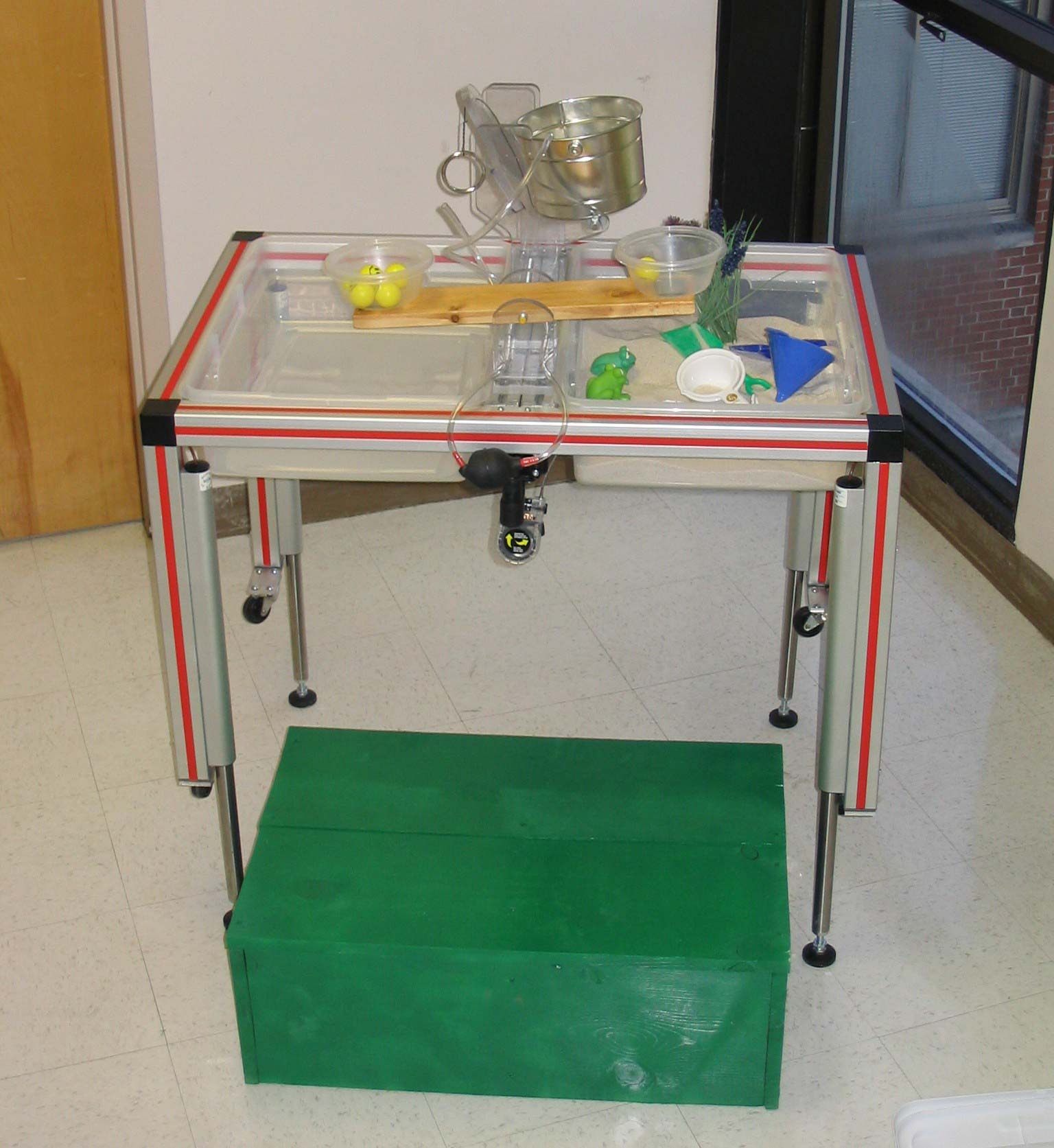
I am quickly trying to make this into a height adjustable stand refer image. With barely any time and very little money and only this 30x60mm aluminium extrusions stand we need the top shelf to move up and down (not much may be just 150mm up and 150 mm down). Since there is barely any money I have decided to use 8 shaft supports mounted to 4 aluminium pillars with 4 linear round shaft to be used as rails and with a single nut machined ball screw d in the centre with some gears and a lever to control the descent but this may need some machined parts which will shoot the price and the lead time.

Are there any other cheaper and quicker options than what I have in mind? May be linear bearings mounted on rails and mount rails onto the extrusion? would that control the reduce the descent speed to much safer level? By descent speed I mean when I want to move the top table from its position by loosening the screw I want the shelf to move slow not just drop rapidly.

Thought I will come to the experts for bright and cheap ideas. Please no smart ass answers like get more money or ask for more time (I tried both).

Thanks in advance.
 
Replies continue below

Recommended for you

You will be disappointed in the linear guides and central ball screw. Fixed linear guides need to be perfect to have any luck. Discuss with yourself what the consequences of misalignment are. There is locational misalignment and angular misalignment and both will cause you distress.

There is nothing new under the sun, however. Someone has figured it out already. You might as well start from that point and not the beginning.

Figure1.jpg
 
Oh cool. That looks good! What is it called as?
 
Make it short and simple, and put it on top of a powered workbench.
The workbench comes with an elevator mechanism and a crank or a motor. They're not cheap, but probably less expensive than the guide rails and stuff you propose.

Or perhaps the guide rails reflect a requirement for a nearly straight trajectory during movement, which you neglected to specify to us. You also didn't mention the load to be translated, usually a significant design selector.

;------------------

When you come in here and ask for help while supplying a grossly inadequate problem description, smart-ass answers are all you deserve.

Further, and especially here, the smart-ass answers are not just intended to insult you, but to wake you up to possibilities you may not have seen, to gently suggest that you provide a little more information because you're there and we're not, and to provide some basis for discussion of what the real problem might actually be.

So, your a priori exclusion of smart-ass answers also excludes what are often the best solutions.


Mike Halloran
Pembroke Pines, FL, USA
 
Thanks dvd and Mike.

Sorry Mike I tried to give as much information as I could. You probably know better than me that in designing you don't get given all the information when you begin with but as we proceed further down the line things get added on! I am not sure about the weight. For now I have planned for the top shelf to carry something around 25kg to 30kg but can change. None of the standards that I am designing to specifies straight trajectory, So I have to presume that its not a requirement. And linear slide bearings were all not that expensive like you have mentioned (still somewhat pricy!). They are around $30 each and the slides about $80 each for almost 1.5m long ones. The only thing I don't like about this is that they have less friction and one way to lock them in required position is with pin or a flange stopper. And once you remove them they will descend rapidly with 25kgs on the top. The table is 1000mm length by 600mm wide and 1300mm high for now. Probably need that 1000mm to 1300mm region to be height adjustable.

Just thought someone else's could make the design even more cheaper.

Thanks again guys!
 
I'm guessing the table linked by dvd uses four electric jackscrews, not intentionally synchronized,
just wired in parallel.

Cheapest thing I can think of is four extensible legs, perhaps extrusions sliding alongside one another,
perhaps nested, driven by four small wire ropes, all terminating on the drum of a small worm-gear winch,
driven by hand crank or electric motor or whatever.

I have seen similar rigs using roller chains instead of cables.
They don't wrap around a drum, they just pass over sprockets on a common shaft.
Tension is maintained by tying the free ends to a heavy bar that goes up and down.
A wormgear reducer drives the shaft.
Roller chain is suprisingly inexpensive in bulk, and easier to terminate than wire rope.


Mike Halloran
Pembroke Pines, FL, USA
 
The table with jackscrews/linear actuators would be a disaster if they are not synchronised eg stepper motors. The common mechanism for this sort of thing is a scissor lift. Link

je suis charlie
 
Thanks guys,

grunt guru - Thats exactly what I suggested, no labour just off shelf and also not that expensive but got rejected because it has to look more professional. Anyway thanks. I will update on what we decided to go with.

Thanks,

V.
 
Status
Not open for further replies.

Part and Inventory Search

Sponsor