Eng-Tips is the largest engineering community on the Internet

Intelligent Work Forums for Engineering Professionals

  • Congratulations waross on being selected by the Eng-Tips community for having the most helpful posts in the forums last week. Way to Go!

Hello All, Trying to do FBD shear 2

Status
Not open for further replies.

Kristina Sornikova

Aerospace
Nov 8, 2016
87
US
Hello All,
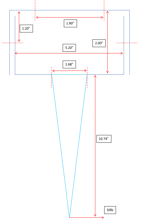
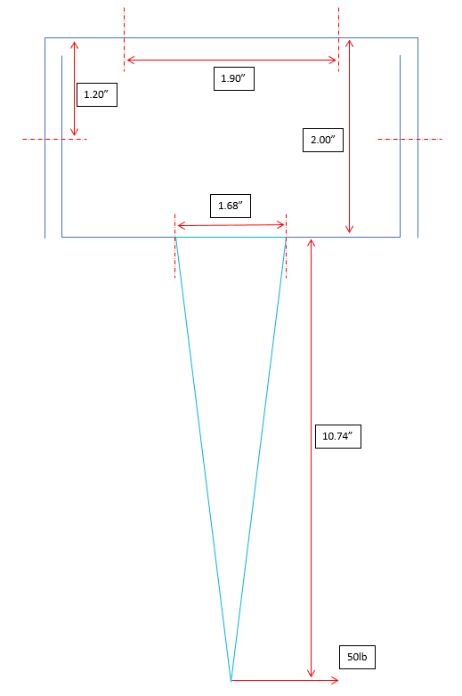
Trying to do FBD shear loads at the side fasteners 1.20" from top. What do you think?
FEM output shows 110lb there each side. Figure not exact to scale.
FBD_wczrzg.png
 
Replies continue below

Recommended for you

Basically it is sum(Moments) = 0 so

50lb (10.74 + 0.8) - Pfast (distance between shear planes) = 0
 
Are those other dashed lines all bolted connections? What are they?
 
Oh I think I see. The inner box connectes to the outer box with bolted connections and the outer box is attached to some stucture. The lever arm is connected to the inner box with bolts. Is there really a gap between the inner and outer boxes at the boted connections as shown or are the plates in contact? Just how are those bolted joints made up?
 
The 1.9" is the distance between top two fastener. In reality there are two on each side of center, but I keep one for simple.
Sorry I missed fastener shear plane dist, it is 5.2" (between inner vertical blue lines).

So Total Fastener Shear Each Side = 50*(10.74+0.8)/5.2 = 25.6lb
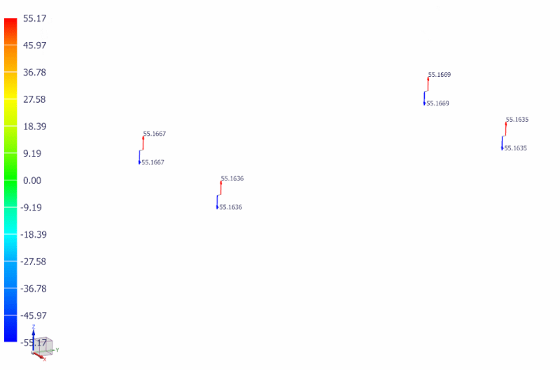
FEM GPFORCE Nodal Z shows Total 2*55 = 110lb each side. Something not add up.

FBD_fyhq2a.png

FEM_wrtoca.png
 
Your made a mistake in your math 50*(10.74+0.8)/5.2 = 110.96

This assumes that the moment is taken up by shear in both the left and right side bolts evenly. I don't think in reality this what will happen. The bolt holes for a shear connection I believe are about 1/16" larger than the bolt diameter. I think what will really happen is that as the inner box wants to rotate about the bolt holes, before contact is made between the bolts and the connecting plate of the boxes (causing the shear force), There will be prying action that will put the left side bolt in tension (prying force) with an associated proped beam reaction force of the outer box on the inner box at the top left acting to the right. On the right side the bottom horizontal plate will be much stiffer than the vertical right side plate so the force of resistance on that side will a be force on the outer box acting on the inner box at the bottom without any prying action on the right side bolt. This assumes plates are rigid and don't bend under bending stress. However the plates are actually flexible (1/16" thick) so loads of outer box on inner box are not point loads but spread out along the vertical plane in a triagular pressure pattern, which I think comes down to a very complicated equation and may be indeterminant.
 
TY so much Snickster. Silly mistake in calculation, so basically I close to FEM result. Very much helpful.
But yeah prying contact can be done in FEM if needed.
 
and then divide by 2 (2 fasteners shown) = 55 ... = FEM !!

"Hoffen wir mal, dass alles gut geht !"
General Paulus, Nov 1942, outside Stalingrad after the launch of Operation Uranus.
 
Status
Not open for further replies.

Part and Inventory Search

Sponsor

Back
Top