Eng-Tips is the largest engineering community on the Internet

Intelligent Work Forums for Engineering Professionals

Hello Guys, I am working on the

Status
Not open for further replies.

ATHS

Structural
Jan 14, 2022
20
0
0
US
Hello Guys,

I am working on the substructure design of a CIP Slab bridge.
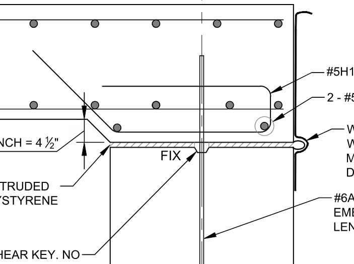
Can anyone suggest how to determine TU/FR (Temperature and Friction forces) for the design of the substructure? I have attached the deck and abutment connection for your reference.
Typically in conventional girder bridges which had a bearing pad, I have used the shear modulus of the bearing pad to determine temperature force on the substructure.

Thanks

 
Replies continue below

Recommended for you

I don't see anything attached, but if you have the slab connected directly to the abutment, the abutment will have to move to accommodate the thermal movements of the slab. The forces on the connection will be dependent on the restraint of the foundation provided by the soil against the abutment, the piles under it, etc.

Rod Smith, P.E., The artist formerly known as HotRod10
 
EOD_vpnuwj.jpg


You should see the snip now. When you say move, do you mean move along the longitudinal axis of the bridge? In the case of the girder slab, we apply the horizontal temperature force on the abutment and then check for sliding, strength, service, and bearing. It should be a similar case here as well. It's just a matter of determining the horizontal temperature force.
 
Is the other end of the bridge free to move or slide? You're not going to restrain the deck from expanding and contracting with temperature changes. If the abutments are restrained against movement by stiff foundation element (concrete drilled shafts, etc.) it'll snap that rebar and the shear key like they were twigs.

Rod Smith, P.E., The artist formerly known as HotRod10
 
Yes, the other end of the deck is free to slide. It's a single span bridge so one end has a fixed connection as shown above and the other end is free to slide. Thermal movement is restrained only in one direction
 
In that case, your lateral force is the total weight of the slab (including all potential future permanent loads) supported by the abutment with the sliding surface, multiplied by the coefficient of friction for the sliding surface. Of course, the loads will have to increased by their proper load factors.

Once you have that force, you'll need to check the capacity of the shear key/reinforcing to be sure it won't shear due to that force.

Rod Smith, P.E., The artist formerly known as HotRod10
 
That connection is pinned - a dowel will not prevent rotation. Furthermore, if the bridge is simply supported (roller and pin), there is no lateral restraint and thermal stresses will self-equilibrate and cause very little - if any - stress.

BridgeSmith already explained how you may account for lateral movement (sliding of the superstructure, essentially, in this case), so I won´t get into that. Note that installing a dowel, such as the one shown in your figure, is not often done for bridges, because the lateral loads (braking forces or sliding forces or other types of forces) may become very large. It is more common to simply let the beam rest on a bearing pad, restrain transverse movement a little, and to ensure that structural self weight is adequate to keep the bridge from sliding in the longitudinal (direction of traffic) direction.
 
Status
Not open for further replies.
Back
Top