Archintrident
Civil/Environmental
- Nov 19, 2024
- 22

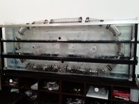
This is the gravity engine.
I know, any competent engineer will immediately say that this is impossible.
He will not even look at my engine.
But I hope that you are curious enough and you will take a look.
The whole structure in the picture is immersed in water (you can use any non-viscous heavy liquid, such as mercury)
The upper level of the device is almost on the surface of the water.
The lower level is at the bottom of the water container.
The device uses the difference in water pressure on the surface of the water and at the bottom of the container.
1) The main part of the machine: A closed hermetic chain of corrugated elements.
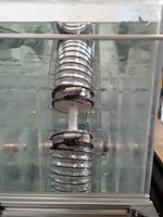
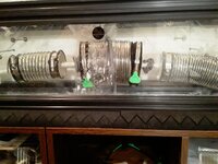
Each corrugated element is made from a piece of corrugated hose 40 cm long in a stretched state and 10 cm in diameter. The piece of corrugated hose is hermetically sealed at both ends. There are holes in both end caps to which connecting tubes are riveted. The tubes connect the corrugated elements into a single closed, hermetic chain. Air is isolated inside the chain of corrugated elements (any gas is possible); air easily flows along the entire chain of corrugated elements, but cannot exit it.
Each corrugated element is easily compressed and stretched from 40 cm to 7 cm. I found the corrugation on Amazon, it can be compressed 7 times! This corrugation easily withstands water pressure and does not compress transversely, only longitudinally. It has a wire that prevents transverse compression.
The connecting tubes between the corrugated elements are rigid and do not change their length of 10 cm and do not compress under water pressure.
2) There are two wheels of a meter diameter.
The chain of corrugated elements is tightly wrapped around these two wheels.
- One wheel is responsible for drowning a section of the chain of corrugated elements and has a gear with a value of one.
- The second wheel is needed to raise a section of the chain of corrugated elements back to the top of the device. This wheel has a gear with a value of 3 relative to the first wheel.
The wheels are fixed in the container on axles. They can only rotate. The gears of the wheels are rigidly connected to each other by a chain, like a bicycle chain. If one wheel rotates, the other one rotates at the same time, but at a different speed.
The first wheel always rotates three times faster due to the gear ratio of 1:3.
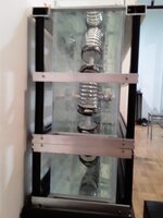
3) A container, a little more than a meter deep. So that the wheels are sunk in water. And the chain of corrugated elements on the upper level could float on the surface of the water.
4) On the lower level of the device, right next to the first wheel, there are supporting rails. They are needed to keep the chain of corrugated elements from floating up to the lower level.
Operation of the device:
I'll start with the lower level.
The chain of corrugated elements arrives at the lower level along wheel 1. On wheel 1, the corrugated elements cannot be compressed, since the wheel has teeth (not shown in the figure) these teeth keep the corrugated elements from premature compression.
After the corrugated element leaves wheel 1, it begins to compress under the pressure of the water. Since the air leaves the corrugated element gradually, the corrugated element retains buoyancy, it is held at the lower level by the rails. The corrugated element has small wheels that slide along the rails. The rails have a slight slope in the direction of the chain movement, this reduces friction.
The slope of the rails should be minimal so that the corrugated elements do not rise high from the bottom of the tank. So as not to lose the force of water pressure.
In the direction of movement from wheel 1 to wheel 2, the corrugated containers are completely compressed.
A fully compressed corrugated element has zero buoyancy. The materials are selected so as to compensate for buoyancy to zero.
Corrugated elements with zero buoyancy are easily pulled back to the bottom and move to wheel 2.
Wheel 2 lifts the section of the corrugated chain with compressed corrugated elements to the top. There is no energy expenditure here, because there is zero buoyancy.
The corrugated elements on wheel 2 cannot be stretched, since the teeth of the wheels prevent them from stretching (the teeth are not shown in the figure).
Having risen on wheel 2 to the top of the apparatus, the compressed corrugated elements leave wheel 2 and begin to swim to wheel 1 on the surface of the water. As they move, the corrugated elements gradually stretch under the air pressure inside the chain.
The air that is currently flowing along the entire chain, squeezed out of the corrugated elements at the lower level of the apparatus.
The corrugated elements come to wheel 1 already full of air and are again sunk by wheel 1 down.
Operating principle:
Compression of the corrugated elements at the lower level by water pressure shortens the length of the section of the chain of their corrugated elements, this causes traction on both wheels.
- Since one wheel has gear 1, it wins against the wheel with gear 3. This makes wheel 2 rotate together with wheel 1, but at a speed three times slower.
- The section of the chain of corrugated elements at the lower level comes to wheel 2 compressed three times and therefore manages to rise from the lower level.
- The section of the chain of corrugated elements at the UPPER level comes to wheel 1 stretched and the faster rotating wheel 1 manages to process the faster running chain of corrugated elements. That is, it quickly drowns the corrugated elements full of air.
The calculation of the traction forces is in the figure.
Designations in the figure:
S - area of the end of the corrugated element. (minus the area of the connecting tube)
V - volume of air in the corrugated element.
0.55 kg - weight of the materials of the corrugated element.
1 m - it's depth of the water at the bottom level of the apparatus.
The gears have 3:1 values.
Also that machine already patented )


