Continue to Site

Eng-Tips is the largest engineering community on the Internet

Intelligent Work Forums for Engineering Professionals

  • Congratulations KootK on being selected by the Eng-Tips community for having the most helpful posts in the forums last week. Way to Go!

Hello people! I have invented a new clean tech! Just look and ask if not understand it.

Archintrident

Civil/Environmental
Nov 19, 2024
22
WhatsApp Image 2024-11-16 at 11.50.27 AM.jpeg
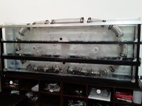
This is the gravity engine.
I know, any competent engineer will immediately say that this is impossible.
He will not even look at my engine.
But I hope that you are curious enough and you will take a look.

The whole structure in the picture is immersed in water (you can use any non-viscous heavy liquid, such as mercury)
The upper level of the device is almost on the surface of the water.
The lower level is at the bottom of the water container.

The device uses the difference in water pressure on the surface of the water and at the bottom of the container.

1) The main part of the machine: A closed hermetic chain of corrugated elements.
Each corrugated element is made from a piece of corrugated hose 40 cm long in a stretched state and 10 cm in diameter. The piece of corrugated hose is hermetically sealed at both ends. There are holes in both end caps to which connecting tubes are riveted. The tubes connect the corrugated elements into a single closed, hermetic chain. Air is isolated inside the chain of corrugated elements (any gas is possible); air easily flows along the entire chain of corrugated elements, but cannot exit it.
Each corrugated element is easily compressed and stretched from 40 cm to 7 cm. I found the corrugation on Amazon, it can be compressed 7 times! This corrugation easily withstands water pressure and does not compress transversely, only longitudinally. It has a wire that prevents transverse compression.
The connecting tubes between the corrugated elements are rigid and do not change their length of 10 cm and do not compress under water pressure.

2) There are two wheels of a meter diameter.
The chain of corrugated elements is tightly wrapped around these two wheels.
- One wheel is responsible for drowning a section of the chain of corrugated elements and has a gear with a value of one.
- The second wheel is needed to raise a section of the chain of corrugated elements back to the top of the device. This wheel has a gear with a value of 3 relative to the first wheel.

The wheels are fixed in the container on axles. They can only rotate. The gears of the wheels are rigidly connected to each other by a chain, like a bicycle chain. If one wheel rotates, the other one rotates at the same time, but at a different speed.
The first wheel always rotates three times faster due to the gear ratio of 1:3.

3) A container, a little more than a meter deep. So that the wheels are sunk in water. And the chain of corrugated elements on the upper level could float on the surface of the water.

4) On the lower level of the device, right next to the first wheel, there are supporting rails. They are needed to keep the chain of corrugated elements from floating up to the lower level.

Operation of the device:

I'll start with the lower level.
The chain of corrugated elements arrives at the lower level along wheel 1. On wheel 1, the corrugated elements cannot be compressed, since the wheel has teeth (not shown in the figure) these teeth keep the corrugated elements from premature compression.
After the corrugated element leaves wheel 1, it begins to compress under the pressure of the water. Since the air leaves the corrugated element gradually, the corrugated element retains buoyancy, it is held at the lower level by the rails. The corrugated element has small wheels that slide along the rails. The rails have a slight slope in the direction of the chain movement, this reduces friction.
The slope of the rails should be minimal so that the corrugated elements do not rise high from the bottom of the tank. So as not to lose the force of water pressure.
In the direction of movement from wheel 1 to wheel 2, the corrugated containers are completely compressed.
A fully compressed corrugated element has zero buoyancy. The materials are selected so as to compensate for buoyancy to zero.
Corrugated elements with zero buoyancy are easily pulled back to the bottom and move to wheel 2.
Wheel 2 lifts the section of the corrugated chain with compressed corrugated elements to the top. There is no energy expenditure here, because there is zero buoyancy.
The corrugated elements on wheel 2 cannot be stretched, since the teeth of the wheels prevent them from stretching (the teeth are not shown in the figure).
Having risen on wheel 2 to the top of the apparatus, the compressed corrugated elements leave wheel 2 and begin to swim to wheel 1 on the surface of the water. As they move, the corrugated elements gradually stretch under the air pressure inside the chain.
The air that is currently flowing along the entire chain, squeezed out of the corrugated elements at the lower level of the apparatus.
The corrugated elements come to wheel 1 already full of air and are again sunk by wheel 1 down.

Operating principle:
Compression of the corrugated elements at the lower level by water pressure shortens the length of the section of the chain of their corrugated elements, this causes traction on both wheels.
- Since one wheel has gear 1, it wins against the wheel with gear 3. This makes wheel 2 rotate together with wheel 1, but at a speed three times slower.
- The section of the chain of corrugated elements at the lower level comes to wheel 2 compressed three times and therefore manages to rise from the lower level.
- The section of the chain of corrugated elements at the UPPER level comes to wheel 1 stretched and the faster rotating wheel 1 manages to process the faster running chain of corrugated elements. That is, it quickly drowns the corrugated elements full of air.

The calculation of the traction forces is in the figure.

Designations in the figure:

S - area of the end of the corrugated element. (minus the area of the connecting tube)
V - volume of air in the corrugated element.
0.55 kg - weight of the materials of the corrugated element.
1 m - it's depth of the water at the bottom level of the apparatus.
The gears have 3:1 values.

Also that machine already patented )
 
Replies continue below

Recommended for you

As this system is being driven by the water it is taking energy from the water. Do you expect to see the temperature of the water to drop?
 
So, if I understand your sketch, the unit is intended to rotate in a counterclockwise fashion, correct? If so, the right wheel spins three times faster than the left wheel as dictated by the gears connected via a bike chain. However, the wheels are also connected via the tightly wrapped corrugated float belt. As you said, the bike chain will force the wheels to spin at a relative speed of 3 to 1. The corrugated float chain will (after fully stretching the floats) restrain the wheels to spin at a relative speed of 1 to 1.

So, you may generate brief rotation as the right wheel stretches the lower corrugated float sections, but once fully extended, the float belt will be fighting against the bike chain, and all rotation will stop. You would still have greater relative buoyancy on the right side of the unit, but again no rotation.
Neat concept, though.
 
I'm pretty sure it's going clockwise, but otherwise totally agree. Apart from all the other issues this will jam it up after about half a turn of the left hand wheel.

There's still no way even if you went 1:1 on the chain that this thing will work but that will kill it.
 
As this system is being driven by the water it is taking energy from the water. Do you expect to see the temperature of the water to drop?
Water only creates pressure due to the gravity of the planet.
Water even will be warmer because the frictions when move.

This device will gradually slow the rotation of the Earth.

The same thing is now done by waves in the oceans.
This will be unnoticeable for hundreds of millions of years.
So I think we have a couple of hundred million years before the rotation of the Earth slows down significantly and the magnetic shield is lost.

But don't worry, I have a better device, but it's not patented yet.
I just want to earn twice)
 
So, if I understand your sketch, the unit is intended to rotate in a counterclockwise fashion, correct? If so, the right wheel spins three times faster than the left wheel as dictated by the gears connected via a bike chain. However, the wheels are also connected via the tightly wrapped corrugated float belt. As you said, the bike chain will force the wheels to spin at a relative speed of 3 to 1. The corrugated float chain will (after fully stretching the floats) restrain the wheels to spin at a relative speed of 1 to 1.

So, you may generate brief rotation as the right wheel stretches the lower corrugated float sections, but once fully extended, the float belt will be fighting against the bike chain, and all rotation will stop. You would still have greater relative buoyancy on the right side of the unit, but again no rotation.
Neat concept, though.
The rotation of the device will be clockwise.
Wheel 1 pushes down the corrugated elements full of air.
Because the pressure exceeds the buoyancy force of the air-filled corrugated elements.
The figure shows that there are only three of them on wheel 1.
And they also have the weight of materials, which reduces their buoyancy.
There is also a gap between the corrugated elements in the form of connecting tubes.
And the water column is always continuous and presses with its entire mass. Therefore, the pressure is capable of drowning the air-filled corrugated elements on wheel 1.

At the bottom, the air-filled corrugated elements, having left wheel 1, begin to be compressed at both ends by the pressure of the water column.
And this gives traction to both wheels.
But one wheel loses due to a weaker gear and rotates together with wheel 1 clockwise.

The compressed corrugated elements have zero buoyancy and easily rise without energy expenditure to the upper level of the apparatus, where the air pressure from the inside pushes them apart and they lengthen three times. Therefore, the chain at the top level runs three times faster and wheel 1 must rotate three times faster to have time to process the chain running onto it.
 
If this is patent protected why haven't you built it yet?

Show us test results. Prove us all wrong.
I'm currently building the apparatus.

I'm a little short of money to rent a house with a pool.
The apparatus works in water, after all.

When I build the apparatus, I'll probably rent a house with a pool by the day.

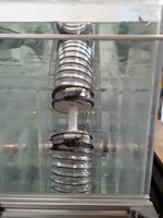
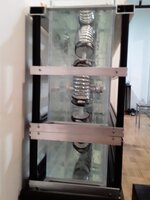
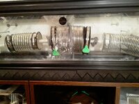
Now I have only managed to build a small stand for research and testing of some critical units.

I have identified many interesting phenomena and effects that interfered with the operation of the device, and eliminated them.
 

Attachments

  • WhatsApp Image 2024-11-02 at 3.54.56 PM.jpeg
    WhatsApp Image 2024-11-02 at 3.54.56 PM.jpeg
    196.6 KB · Views: 25
  • WhatsApp Image 2024-11-02 at 3.54.16 PM.jpeg
    WhatsApp Image 2024-11-02 at 3.54.16 PM.jpeg
    132.9 KB · Views: 22
  • WhatsApp Image 2024-11-02 at 3.54.37 PM.jpeg
    WhatsApp Image 2024-11-02 at 3.54.37 PM.jpeg
    106.3 KB · Views: 19
  • WhatsApp Image 2024-11-07 at 7.16.21 PM.jpeg
    WhatsApp Image 2024-11-07 at 7.16.21 PM.jpeg
    276.1 KB · Views: 25
I'm pretty sure it's going clockwise, but otherwise totally agree. Apart from all the other issues this will jam it up after about half a turn of the left hand wheel.

There's still no way even if you went 1:1 on the chain that this thing will work but that will kill it.
No, it won't jam.
Because the chain tends to lengthen at the top of the machine due to its stretching by the air pressure that comes along the chain from below from the compressed corrugated elements.

And at the bottom, the chain shortens its length by three times due to compression.
This is exactly why different wheel rotation speeds are needed.

Wheel 1 receives a chain moving three times faster, which is additionally accelerated by the lengthening. Therefore, it rotates three times faster than wheel 2.

Wheel 2 processes a chain that has shortened three times and everything is fine with it too. That is why wheel 2 is three times slower.

For proof:
This is a very similar device.
The nitinol spring imitates the operation of my device.
It also shortens its length on one side and lengthens on the other.
And the device does not jam due to the difference in the rotation of the wheels.

This device works on the difference in temperatures.
Whereas my machine works on the difference in pressure.

But in general, the principle of operation of the mechanisms is the same.
I had to bend the device so that one side was in hot water, the other side in cold.
 

Attachments

  • nitinol.mp4
    1.8 MB
  • WhatsApp Video 2024-09-26 at 10.55.15 PM.mp4
    3.1 MB
I'm currently building the apparatus.

I'm a little short of money to rent a house with a pool.
The apparatus works in water, after all.

When I build the apparatus, I'll probably rent a house with a pool by the day.

Now I have only managed to build a small stand for research and testing of some critical units.

I have identified many interesting phenomena and effects that interfered with the operation of the device, and eliminated them.
Please post the prototype in motion. Good luck with your build. I applaud your action to prove your concept!
 
The rotation of the device will be clockwise.
Wheel 1 pushes down the corrugated elements full of air.
Because the pressure exceeds the buoyancy force of the air-filled corrugated elements.
The figure shows that there are only three of them on wheel 1.
And they also have the weight of materials, which reduces their buoyancy.
There is also a gap between the corrugated elements in the form of connecting tubes.
And the water column is always continuous and presses with its entire mass. Therefore, the pressure is capable of drowning the air-filled corrugated elements on wheel 1.

At the bottom, the air-filled corrugated elements, having left wheel 1, begin to be compressed at both ends by the pressure of the water column.
And this gives traction to both wheels.
But one wheel loses due to a weaker gear and rotates together with wheel 1 clockwise.

The compressed corrugated elements have zero buoyancy and easily rise without energy expenditure to the upper level of the apparatus, where the air pressure from the inside pushes them apart and they lengthen three times. Therefore, the chain at the top level runs three times faster and wheel 1 must rotate three times faster to have time to process the chain running onto it.
Two questions:

1. What is generating the driving force to rotate wheel 1 (the right wheel) clockwise? The inflated sections will create buoyant counterclockwise torque on wheel 1 encouraging it to rotate in a counterclockwise fashion.

2. How can the belt slip along wheel 2 and still impart torque to wheel 1? Based on your buoyancy calculations, your wheels will not lose grip and slip between the float belt and the wheels. The torque generated from only about 1 meter of liquid depth is not great enough to overcome the kinematic (much less static) friction between the belt and the wheels assuming the belt is reasonably tight along the wheels. Moreover, even if you loosened the belt to allow it to slip, a slipping belt would be unable to impart any significant torque to the wheels.

Not a question but more of a comment, I believe you are operating under a misconception regarding the "stretch rate" required by the belt. Let's assume that the belt is 5 meters long in its fully compressed state. Now let's say the belt can be stretched to be 50 meters long when fully extended. If your wheels are each 1 meter in diameter, after one full rotation of wheel 2 (the left wheel), wheel 2 has driven 3.1 meters of belt. Wheel 1 would need to begin stretch the belt to drive its required 9.4 meters of belt (three times more than wheel 2). If the unit theoretically spun for 30 continuous rotations, wheel 2 would drive 94.2 meters of belt while wheel 1 would need to drive 282.7 meters of belt to maintain equilibrium. Wheel 1 would need to have cycled 188.5 meters of belt more than wheel 2. But the belt can only stretch to 50 meters long.

Do you understand my point?

You never "get back" the stretched portion of line. The belt stretches continuously until it has reached its maximum length (using my rough numbers, 50 meters). At that point, either the belt rips in half, the whole unit locks up and stops rotating, or the belt slips around the wheels (without rotating the wheels).
 
Please post the prototype in motion. Good luck with your build. I applaud your action to prove your concept!
I will definitely post a video of the working device when I build it.
I work a lot to earn money for it.
And so the building work is not moving quickly.
 
Two questions:

1. What is generating the driving force to rotate wheel 1 (the right wheel) clockwise? The inflated sections will create buoyant counterclockwise torque on wheel 1 encouraging it to rotate in a counterclockwise fashion.

2. How can the belt slip along wheel 2 and still impart torque to wheel 1? Based on your buoyancy calculations, your wheels will not lose grip and slip between the float belt and the wheels. The torque generated from only about 1 meter of liquid depth is not great enough to overcome the kinematic (much less static) friction between the belt and the wheels assuming the belt is reasonably tight along the wheels. Moreover, even if you loosened the belt to allow it to slip, a slipping belt would be unable to impart any significant torque to the wheels.

Not a question but more of a comment, I believe you are operating under a misconception regarding the "stretch rate" required by the belt. Let's assume that the belt is 5 meters long in its fully compressed state. Now let's say the belt can be stretched to be 50 meters long when fully extended. If your wheels are each 1 meter in diameter, after one full rotation of wheel 2 (the left wheel), wheel 2 has driven 3.1 meters of belt. Wheel 1 would need to begin stretch the belt to drive its required 9.4 meters of belt (three times more than wheel 2). If the unit theoretically spun for 30 continuous rotations, wheel 2 would drive 94.2 meters of belt while wheel 1 would need to drive 282.7 meters of belt to maintain equilibrium. Wheel 1 would need to have cycled 188.5 meters of belt more than wheel 2. But the belt can only stretch to 50 meters long.

Do you understand my point?

You never "get back" the stretched portion of line. The belt stretches continuously until it has reached its maximum length (using my rough numbers, 50 meters). At that point, either the belt rips in half, the whole unit locks up and stops rotating, or the belt slips around the wheels (without rotating the wheels).
1. Wheel 1 and Wheel 2 are both attracted when the corrugated elements are compressed and the chain of them begins to shorten under the pressure of the water.
Both wheels tend to rotate towards each other.
Because the compressed chain of corrugated elements pulls them both towards itself.

But the wheel 1 has a stronger gear and forces wheel 2 to rotate clockwise.

result: The force that makes wheel 1 rotate is the water pressure on the corrugated elements at the lower level of the apparatus.

Fully stretched corrugated elements (3 pieces on wheel 1) have a buoyancy lower than the pressure of a solid water column.
Because there are gaps between them in the form of connecting tubes. And there is also the weight of the materials from which the corrugated elements are made and this weight reduces buoyancy.
The figure shows the volume of 3.14 l and the weight of 0.55 kg for each corrugated element on wheel 1.

2.Nothing slides on the wheels.
Both wheels have teeth that prevent the chain of corrugated elements from slipping.
Also, the teeth do not allow the corrugated elements to compress or stretch.
(The teeth are not shown in the picture) but they are mentioned in the description.

The chain of corrugated elements is made in such a way that it is able to stretch and compress three times.
And the gears also have a ratio of 1:3.
So everything is in harmony.

Moreover I conducted experiments and derived the ratios of chain lengthening and shortening and the ratio of gears on the simulator.
Attached video.
Everything works.
On this simulator, the role of the teeth on the wheels is performed by rubber rims, they prevent slipping quite well even without teeth.
 

Attachments

  • WhatsApp Video 2024-09-26 at 10.55.15 PM.mp4
    3.1 MB
  • nitinol.mp4
    1.8 MB
1. Wheel 1 and Wheel 2 are both attracted when the corrugated elements are compressed and the chain of them begins to shorten under the pressure of the water.
Both wheels tend to rotate towards each other.
Because the compressed chain of corrugated elements pulls them both towards itself.

But the wheel 1 has a stronger gear and forces wheel 2 to rotate clockwise.

result: The force that makes wheel 1 rotate is the water pressure on the corrugated elements at the lower level of the apparatus.

Fully stretched corrugated elements (3 pieces on wheel 1) have a buoyancy lower than the pressure of a solid water column.
Because there are gaps between them in the form of connecting tubes. And there is also the weight of the materials from which the corrugated elements are made and this weight reduces buoyancy.
The figure shows the volume of 3.14 l and the weight of 0.55 kg for each corrugated element on wheel 1.

2.Nothing slides on the wheels.
Both wheels have teeth that prevent the chain of corrugated elements from slipping.
Also, the teeth do not allow the corrugated elements to compress or stretch.
(The teeth are not shown in the picture) but they are mentioned in the description.

The chain of corrugated elements is made in such a way that it is able to stretch and compress three times.
And the gears also have a ratio of 1:3.
So everything is in harmony.

Moreover I conducted experiments and derived the ratios of chain lengthening and shortening and the ratio of gears on the simulator.
Attached video.
Everything works.
On this simulator, the role of the teeth on the wheels is performed by rubber rims, they prevent slipping quite well even without teeth.
Thanks for the clarification. I think I better understand your intended process.
Unfortunately, I don't think you are understanding my point. You said, "The chain of corrugated elements is made in such a way that it is able to stretch and compress three times." My point is that the corrugated belt will need to be able to extend three times its current length per rotation. After one full rotation of wheel 2, wheel 1 will have stretched the upper portion of the belt three times its original length. After two rotations, that upper section of belt will have been stretched six times its original length. After 3 rotations, nine times the original length, and so on.

Your video of the nitinol heat engine works in this fashion of stretching and shortening the wire because it is not constrained by a rigid chain operating at a higher gear ratio like your proposed gravity engine.

Does this help clarify my point?
I understand you.

But the nitinol motor also has gears with a ratio of 1:3
It's just that in my device the gears are connected by a chain because they are at a distance.
And in the nitinol motor the gears are brought together because the device is bent and wheel 1 and wheel 2 are now almost next to each other and almost coaxial with a small offset so that the gears can contact directly.
The nitinol simulator is bent and has auxiliary wheels because hot or cold water cannot be placed one above the other.

Every time after stretching, the chain is compressed again in front of the second wheel, and stretched again in front of the first wheel.

The chain of corrugated elements not only stretches, it also compresses back.

The cycle of one complete revolution around both wheels consists of one stretch and one compression.

So in general the chain maintains its length constant.
 

Attachments

  • WhatsApp Video 2024-09-26 at 11.06.42 PM.mp4
    3.6 MB
I understand you.

But the nitinol motor also has gears with a ratio of 1:3
It's just that in my device the gears are connected by a chain because they are at a distance.
And in the nitinol motor the gears are brought together because the device is bent and wheel 1 and wheel 2 are now almost next to each other and almost coaxial with a small offset so that the gears can contact directly.
The nitinol simulator is bent and has auxiliary wheels because hot or cold water cannot be placed one above the other.

Every time after stretching, the chain is compressed again in front of the second wheel, and stretched again in front of the first wheel.

The chain of corrugated elements not only stretches, it also compresses back.

The cycle of one complete revolution around both wheels consists of one stretch and one compression.

So in general the chain maintains its length constant.
Unfortunately, you do not understand me.
The nitinol engine has a single chain/belt which stretches and compresses throughout the cycle.
The gravity engine also has a corrugated belt which stretches and compresses throughout the cycle.
However, the gravity engine has a second chain which does not stretch and compresses throughout the cycle.
This rigid chain forces the upper portion of the corrugated belt to be in ever increasing tension and the lower portion to be in ever increasing compression.

I'm not sure how else to explain it. If you just make a quick miniature model of your system with cardboard wheels and rubber bands for the belt and chain, you will see what I mean.
My machine and the nitinol simulator have the same gear ratio of 1:3
If you unbend the nitinol simulator and connect the gears with a chain, the result from the difference in revolutions will be the same.

A chain drive between wheels is the absolutely the same as a direct clutch between gears.

It can also be a cardan drive between gears.

This is a constant value, it does not increase with the number of revolutions.

Every time wheel 1 rotates three times, wheel 2 makes one revolution.

And the chain of corrugated elements always adjusts to these revolutions, lengthening and shortening by three times.

Which is demonstrated by the nitinol simulator of my machine.
 
In case only my report doesn't work, then please don't respond again and just report this as a perpetual motion device so it gets deleted.
 
In case only my report doesn't work, then please don't respond again and just report this as a perpetual motion device so it gets deleted.
This is not a perpetual motion machine.

This engine uses the gravity of the entire planet.
The effect is almost similar to the consequences of an orbital maneuver, when a spacecraft takes some of the energy from the planets during acceleration with the help of a maneuver near the planet.
But due to the incomparable masses, the planet hardly notices its slowdown during the acceleration of the spacecraft.

My device gradually slows down the rotation of the planet.
And the slowdown is so insignificant that even if all of humanity switches to generating energy with this device, it will take hundreds of millions of years to notice any measurable slowdown in the rotation of the Earth due to the impact of my devices.

At the moment, ocean waves slow the rotation of the planet. And it is unlikely that humanity will quickly create enough my devices to exceed the quantitative effect of ocean waves.

And I'm surprised that the admin allowed this post!
He must be a real engineering genius and he probably understood how everything works!
 
Last edited:
Apart from all the other things wrong with this device, one is that you seem to be using a factor of three for everything, including the compression of your mysterious tube things.

If you start at the top side with air at atmospheric pressure and the flexible tube things at a neutral length and then submerge them in water 1m deep you have a pressure of 0.1 barg (give or take). That will compress your axially flexible volume by 10% only, not 300%

Same when it comes out of the water- it will expand once it releases itself from the cog thing by 10% back to its original length.

Your picture of the string of these things seems to show a much bigger variation in length which looks like it is being physically stretched hence internal pressure < atmospheric then compressed mechanically by a factor of 2 or 3 so pressure would be much more than the pressure exerted by the depth of water. One section seems to be twice the length of some of the others??
 

Part and Inventory Search

Sponsor