Continue to Site

Eng-Tips is the largest engineering community on the Internet

Intelligent Work Forums for Engineering Professionals

  • Congratulations waross on being selected by the Eng-Tips community for having the most helpful posts in the forums last week. Way to Go!

help for electricity distribution (HTA) through underground cables (6 circuits)

Status
Not open for further replies.

Ennajjar

Electrical
Jul 20, 2015
13
I'm studying Electrical engineering at faculty.I will be pleased If you can guide me and give me advices and directions to take for resolving some problems I meet during my internship.

Actually, I'm working on a project about a medium voltage electricity distribution (HTA) through underground cables. The first problem I met is concerning the induced current that flows in the cable screen; it is very high and causes the burning of cables and ends. the second problem is about the imported power, at the output we find it less than what is supposed to be posted.

I try to calculate the current following the IEC 60287 norm in each circuit for different mode. I need to know how can I calculate this current with the purpose to raise it by varying factors that impact on it. Also I don't know how can I use this norm for 6 circuits.

I will be very thankful If you can guide me and help me in my work.
Thanks in advance.

Mehdi Ennajjar
 
Replies continue below

Recommended for you

In order to get a suitable answer, in my opinion, you have to be more specific.
I think you are speaking about 3*6 single-core medium voltage cables- armored or not-shield grounded [earthed] at one end or both ends-at distance of at least 0.25 m each other in single row-or more and so on.
The cables will run directly buried in the soil or in conduits or concrete duct bank. If you will follow a correct configuration of phases the unbalance between currents in the cables of the same phase will be minimum. If not you have to calculate the current unbalance according to IEC 60287-1-3.
 
for calculate the current
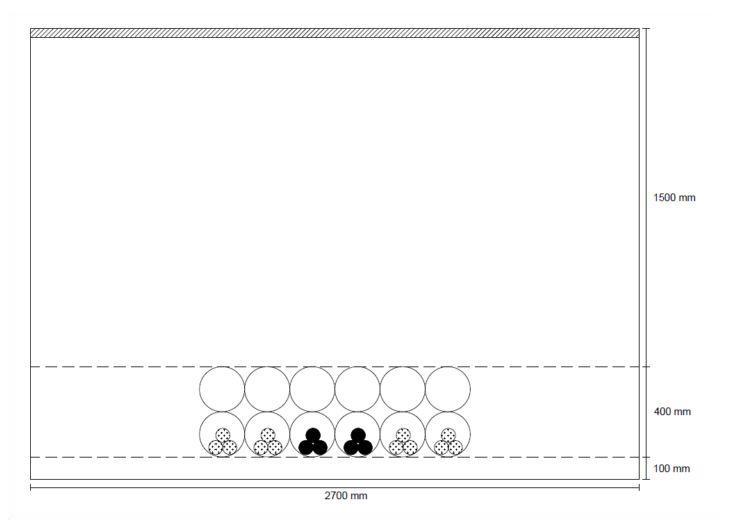
condition for laying cables:
6_circuit_nx5hwd.jpg

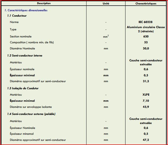
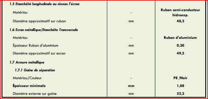
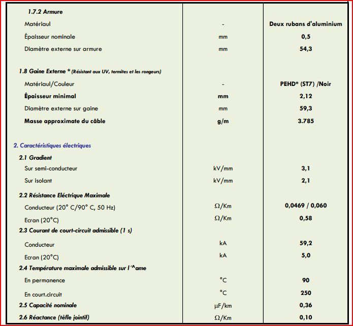
Synthetic insulated single core cables for rated voltages
Uo / U = 18/30 kV (Um = 36 kV)
 
the system must be balanced
so I use the IEC 60287 2-1 ?
I'm blocked on calculates External thermal resistance T4'''
(about the method Neher-McGrath is for cables embedded in the concrete?,or I can use for my situation?)
 
If that sketch shows the phases running in an A-A-B-B-C-C configuration you should reconsider. Put one cable from each phase in each duct.
 
From IEC 60287-2-1 you have to follow:
2.2.7.3 External thermal resistance of the duct (or pipe) T4′′′
What is not clear in this chapter?
From my VB program :
If concrete HORIZ_W >= VER_H then:
YNN = HORIZ_W[big]; XNN = VER_H[small]
ln(rb) = 1 / 2 * XNN / YNN * (4 / pi() - XNN / YNN) * Ln(1 + YNN ^ 2 / XNN ^ 2) + Ln(XNN / 2)
rb=exp(ln(rb))
See :
Figure 1 – Diagram showing a group of q cables and their reflection in the ground-air surface
fk = fk * LI(i, j) / LD(i, j) LI(i,j)=d'pk virtual distance between duct i and j
LD(i,j)=dpk actual distance between duct i and j.
UE = 2 * LS(i) / DDEXT
LS(i)=Lp the vertical distance from duct center line to soil surface for duct i
DDEXT=outside duct diameter[m]
TCONC = 1 / 2 / pi() * ROC * Ln((UE + Sqrt(UE ^ 2 - 1)) * fk) / 100
ROE=earth resistivity[ohm.m],ROC=concrete resistivity[ohm.m]
ug = LS(i) * 1000 / rb
TEARTH = nload / 2 / pi() * (ROE - ROC) * Ln(ug + Sqrt(ug ^ 2 - 1)) / 100
nload=number of loaded ducts[1 of 3 cables]
T”4=TCONC+TEARTH
Let’s say 6 pvc duct of 6” [168 mm outside dia] 250 mm center to center line distance
Let’s say cable of 30 kV 300 mm^2 copper conductor XLPE insulated shield grounded at one end.
concrete 1 k.m./W earth 0.9 k.m./W 25oC 1.75 m depth concrete duct bank 300*1500 mm.
The maximum allowable current per one conductor 320 A.

 
In my situation I don't have concrete. Ducts are similar and puted in earth directly.
Can I use this procedure even if I don't have concrete? If not what can I do?
Thank You.
 
If ROC=ROE then TEARTH will be TCONC where instead of ROC you will put ROE. The second part will be 0.
Since you have 2700 mm available trench width you may keep 450 mm distance center-line-to center line but since the conduit stays directly on sand the sand will dry and it is indicate to take 2.5 k.m/W earth thermal resistance. See 2.2.6.1 Buried troughs filled with sand.
So the above cable maximum permissible current [ampacity] will be only 220 A.
 
cable of 30 kV 630 mm2 aluminium conductor XLPE
for ROC=ROE
T'''4=1 / 2 / pi() * ROE * Ln((UE + Sqrt(UE ^ 2 - 1)) * fk) / 100
ROE= 1,5 C.M/W
UE = 2 * LS(i) / DDEXT
LS(i)= 1800 mm
DDEXT= 200 mm

==> UE =18
FK=3147,04138 (with 450 mm between ducts )

T"'4=0,02662067104
T'4=0,24118306
T''4=0,050808318
T4 = T'4 + T"4 + T"'4
T4=0,318611649

I=Sqrt{ΔӨ-WD*(0,5*T1+T2+T3+T4)/(R(T1+(1+λ1)*T2+(1+λ1+λ2)*(T3+T4))}
ΔӨ=90-25
WD=0,018
T1=0,25
T2=0,024
T3=0,06
RAC 90°C=0,0000624
λ1=0,044
λ1=0,087

I=1280,286232 A
I Think that it is great!!


In my opinion, if 1280 A it is the total phase current, it seems to me o.k.[I did not follow quite your calculation but it seems to me earth resistivity it has to be 2.5 k.m./W –not 1.5.]
 
Now I saw one of the mistakes. Sorry, I forgot to say in the following formula ROE=150 c.cm/W and it is not 1.5 c.m/W [or you don’t need to divide by 100!]
T'''4=1 / 2 / pi() * ROE * Ln((UE + Sqrt(UE ^ 2 - 1)) * fk) / 100
It seems to me when I transferred part of formulas from Neher&McGrath to IEC I did not change the units. My mistake!
 
I found another mistake[sorry, this is yours this time]:
According to IEC 60287-1-1 ch.1.4.1.1 AC cables:
I=Sqrt{ΔӨ-WD*(0,5*T1+T2+n(T3+T4)/(R(T1+(1+λ1)*T2+n(1+λ1+λ2)*(T3+T4))}
You missed n=3 on above formula.
 
Another –my mistake-just for record:
ROE=earth resistivity[ohm.m],ROC=concrete resistivity[ohm.m]
It is not earth resistivity but earth thermal resistivity [k.m/W] or [Co.cm/W]
 
In my opinion, if the cable is as in attached table and the conditions are as you described it:
-1.8m center line conduit depth, 50 Hz, 1.5 k.m/W, 25 oC,6* 8" pvc conduits,450 mm appart-
then you'll get 303 A ampacity per cable that means 6*303=1818 A/phase.[the maximum temperature of 90oC will be of no.3 and 4 conduit conductors.]

 
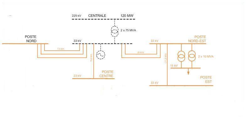
here is my power circuit
CIRCUIT_DE_PUISSANCE_r9pd5d.jpg

the specifications mention that 30MW should be carryed to the North post(poste nord)
but 303A isn't enough
 
At first you have to follow ScottyUK recommendation and to select A-B-C [or R-S-T] sequence phases in each of all 6 conduits- in order to mitigate the proximity effect and currents unbalance.
In my opinion, if you have 6 parallel cables per phase, your total permissible current will be 303*6=1818 A/phase .This will be sqrt(3)*33*1.818=103.9 MVA. If power factor [cos(Fi)]=0.8
you'll get 83 MW power. However, what do you need it is only 30 MW.
If it is only one cable per phase and all three phases are in the same conduit then only 495 A
it will be the maximum. If it will be a single cable per conduit at 450mm distance then 599 A it will be the maximum.
 
The three phases happen in the same duct (1 duct contains 3 cables== 1 circuit).
Circuits are buried together in the power station then they are separated to be diffused in their designated post.
The north post is connected to 3 circuits.
So if one circuit contains 495 Then the three same circuits will contains 3* 495= 1485

= => S=SQRT(3)* 33*1485=84,87 MVA
AND P=67,9 MW
It is true??
 
The presence of other 2 conduits will reduce the maximum permissible current.
If you can keep 1200 mm distance between conduits [center line to center line] then 412.5 A will be the maximum [3*412.5=1237.5 A, 70.7 MVA, 56.5 MW].
 
same methode for calculus I ?
I=Sqrt{ΔӨ-WD*(0,5*T1+T2+n(T3+T4)/(R(T1+(1+λ1)*T2+n(1+λ1+λ2)*(T3+T4))}
 
Status
Not open for further replies.

Part and Inventory Search

Sponsor