Continue to Site

Eng-Tips is the largest engineering community on the Internet

Intelligent Work Forums for Engineering Professionals

  • Congratulations KootK on being selected by the Eng-Tips community for having the most helpful posts in the forums last week. Way to Go!

Help! New Engineer Need help identifying CV shaft spline standard 9

Status
Not open for further replies.

Speedracerfast

Automotive
Dec 30, 2019
29
Hi everyone,

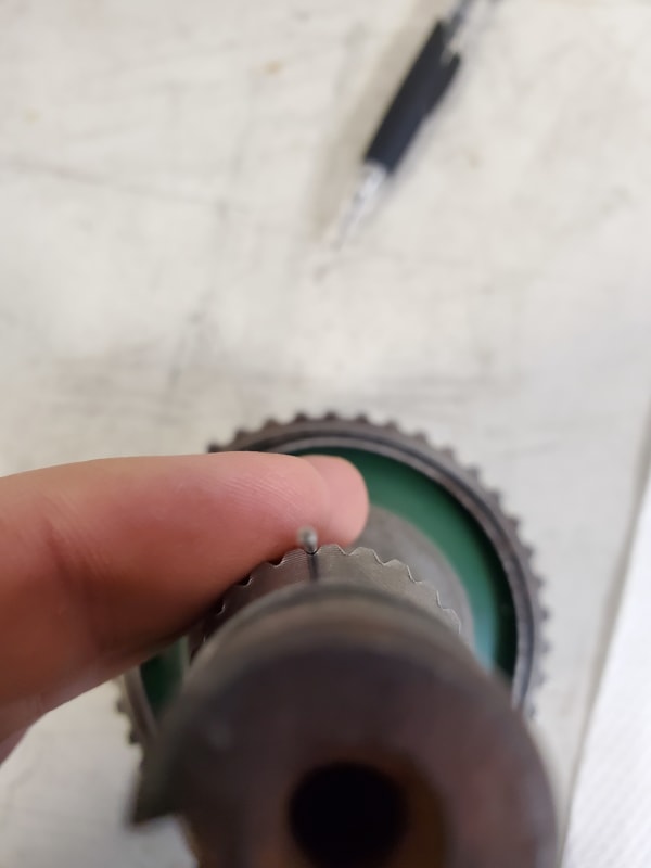
My first post here. I am a young engineer and just got my first job out of college as a design/reverse engineer for a aerospace company. Currently I am doing my own automotive projects on the side and having trouble identifying this spline. Long story short, I am retrofitting tapered roller bearings into a hub and spindle for a old Isuzu. I have virtually everything complete besides matching this spline standard. I've been beating my head on this part for a bit now, and would appreciate any insight. Also I can't find a copy of any JIS spline standards that don't cost upwards of +$350!

Pics attached too.

I am pretty sure it is JIS-D-2001 or JIS 1603 B. Although it is probably a JIS-D-2001 because its a cv shaft, meaning major diameter fit. I could be wrong about it being a JIS standard because my research points out that GM had a lot to do with building this car.

Spec/Dimensions I've found below via optical comparator:

Internal Spline
24 Teeth
Small ID (tip to tip): 0.975"
Big ID (root to root): 1.06"
Tip width : 0.027"
Root Width : 0.017"
Angle of tooth (paint drawing attached for clarification): 40-50 degrees


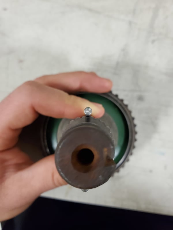
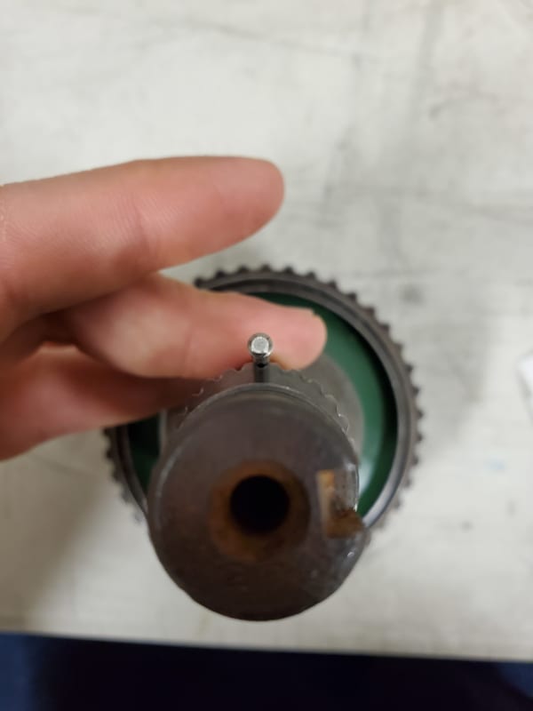
 
 https://files.engineering.com/getfile.aspx?folder=b99d5aca-da44-44ce-9934-2092f7a9e32a&file=20191210_071505.jpg
Replies continue below

Recommended for you

I think you may need to take some measurements between pins. Using several size pins could also help determine if it is an involute or not. Although if it's GM there's a decent chance it's not a standard spline. I would recommend reading up on involute splines so you know what you're looking for with major/minor diameters, circular space width, and pressure angle etc.
 
Thanks lfw618. I am familiar with the 3 gauge pin method, but only for something external, I only have the internal spline here. I could track down the CV shaft and do it on that.

Why since GM it won't match a standard spline? Do they have their own spline standards or something?
 
Measurement between or over pins is just two pins. Again I think you would benefit from reading up more on involute spline terminology. There is a lot of information readily available on the internet without needing to buy a standard.

Automotive is one of those industries where non-standard splines are often justified. GM often uses non-standard splines in their drivetrain parts in my experience.
 
Yeppers that's a spline all right ,
3 wire check wont work , only two wires since truncated
obtain dentist two part mold, and cast a mold or if you can
measure circular pitch, and with the mold measure the base pitch.
look at charts for combination to get a Module or DP. that has the same CP & Base Pitch..
it looks like a 45 deg spline.

do you have access to a CNC gear checker?
 
Thanks mfgenggear! I am working on getting the mating CV/axle shaft which should be in my hands soon (a nearly brand new one.. super lucky!).

No access to CNC gear checker unfortunately. I do have access to optical comparator, vision system, and x2 CMMs.

I will come back with my results soon.

 
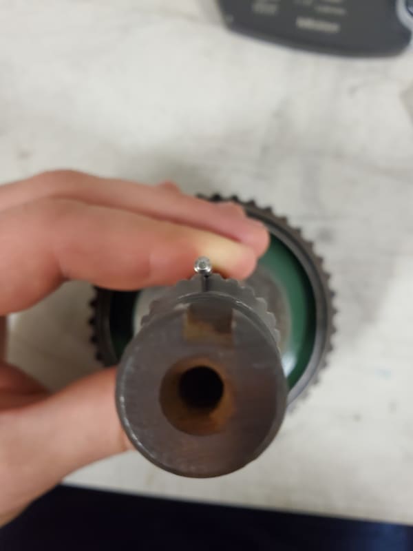
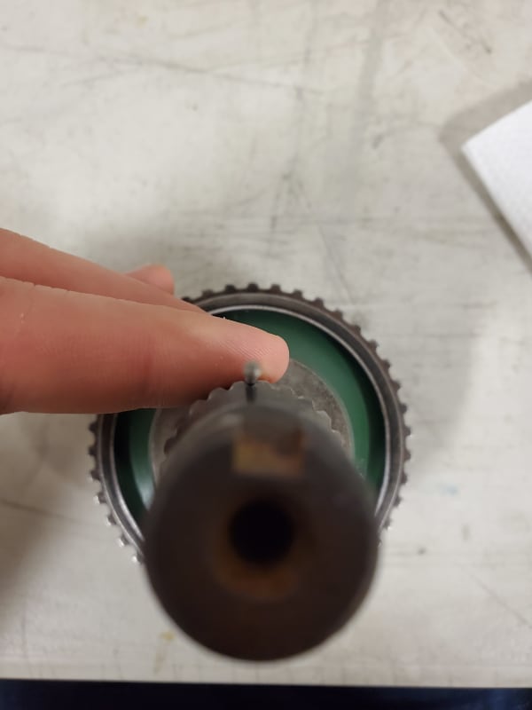
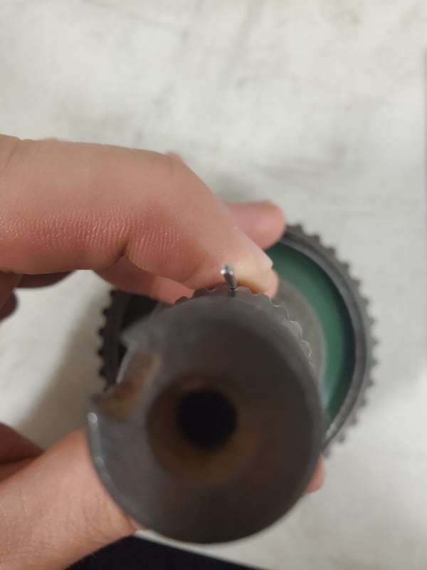
I have attached more pics of the spline too for reference.

thumbnail_20191213_080000_zteymr.jpg


spline_2_iholyr.jpg
 
There used to be a guy around here, known by the name of gearcutter /Ron Volmershausen, Australia/, very knowledgeable when it came to the JIS spline standards, but he seems to be no longer with us.
There is only one involute that meets all the conditions you have mentioned, so I have calculated it.
Check out this template 10:1 You may want to print it out (or some section(s) of it) in a scale matching that of your optical comparator and see if it fits, and let us know.
 
Hi everyone,

Sorry for the delay. Also thanks spigor! I'll give that a shot next week.

I got the CV shaft in (male mating spline) and did some over pine measurements. I will pop it on the vision system tomorrow to confirm #'s but I thought I'd share the raw data (+/- 0.00005"). Again any insight is greatly appreciated. I will crunch numbers asap and post findings here:

1) Pin one dia= .1199" , Pin two dia= .1199" --> 1.2246" across/ 1.22495" across
2) Pin one dia= .1080" , Pin two dia= .1079" --> 1.1973" across/ 1.19735" across
3) Pin one dia= .09200 , Pin two dia= .09200" --> 1.1605" across/ 1.1601" across
4) Pin one dia= .07190" , Pin two dia= .07195" --> 1.11320" across / same
5) Pin one dia= .06290" , Pin two dia= .06295" --> 1.09135" across/ same
6) Pin one dia= .05485", Pin two dia= .05485 --> 1.0726" across / 1.07300" across
7) Pin one dia= .04480" , Pin two dia= .04485" --> 1.04770" across/ same

Pictures:
1)
1_hstznf.jpg

2)
2_zv39vs.jpg

3)
3_gnlt6v.jpg

4)
4_tnkchz.jpg

5)
5_cjpfnd.jpg

6)
6_tbzhb3.jpg

7)
7.1_hmo2tl.jpg


Thanks again everyone.
 
Ok I take it back, that's probably a standard spline. Those measurements seem consistent with a 24DP 45 degree PA. Have you been able to calculate circular tooth thickness from those measurements? I'd look at getting ANSI B92.1 to confirm. With calculated tooth thickness and the standard you can guess the tolerance class (maybe class 6?).
 
Sorry all,

Got the flu and been sleeping feels like for 3-4 days straight. Anyways Thursday I remeasured the female spline on the vision system and comparator to match numbers; my initial measurements were off.

Diameter Root = 1.0627"
Diameter Tip = .9761"
Tip width = .0274" (across treated as straight line just for calculation sanity checks)
Root Width = .0168" (same; across treated as straight line)

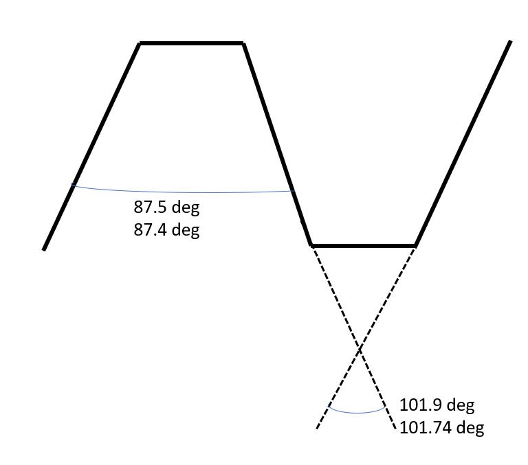
Angles of teeth I obtained below in the figure:
angle_screenshot_lzg2zu.jpg


--------------------------------------------------------------------------------------------------------------------------------
As far as calculations go, I am going to go ahead and bite the bullet here, and look stupid on the internet. The only calcs I am confident with are with module and pressure angle. I didn't to mention that I am up to speed with gear terminology because I was also working on a custom gear project for my Mazda prior, however little reverse engineering was involved, yet.

PA = 45 degrees (calculated via male shaft physical measurement and CAD model female spline measurement to confirm via method here:
Circular pitch = 1.0194"... is it fair here to take the circle directly between Diameter Root = 1.0627" Diameter Tip = .9761" if PA is 45 degrees?

Module = .042475

As far as measurement over two pins; I am very lost here. I can't confidently follow the math in write ups online because most call of a known pitch, which I don't have. ANSI B92.1 is close to $100, and I am hesitant to buy another standard I'll maybe not need or use much (last time I spent $300+ on standards I barely needed for my gear project).

I am not asking to be spoon fed (unless you want to haha) but maybe a sample calc from the data I provided?

Also I was thinking since this spline most likely be EDM'ed, I can provide a drawing (similar to spigor provided above)and run a test cut on a 1/4" plate. Then I an test fit on the CV shaft and see if it has similar backlash and fit.

Sorry for the long post everyone. I am getting a little desperate as my business partner for this project seems to be loosing faith.
 
For reverse calculation (tooth thickness from the size over pins) check this:
Splines and spur gears have helical angle zero; for the helical gears it will be non-zero value. Because the helical angle changes by the diameter, both the angle and dia where it is measured is important for the calculations.
But this helix stuff was just my "spoon" of generic info for you. For the helix angle entry you need to enter there 0 (zero).
Another "spoon": The pressure angle of a spline/gear is defined at the PD too, because it too differs by the dia... Confused enough?
Please be aware that all of the discussion and calculations mentioned here are valid for involute splines.
 
can you measure the major dia of the male spline and let me know if it measures between 1.042 / 1037 also could you take a measurement across seven teeth and let me know how close it is to .7583 / .7574. Your initial measurements are pointing towards a ANSI B92-1-1970 (revised 1993) Table 57 Class 5.
 
Google search a web site that will create a free dxf file of the internal spline geometry.
Open with a cad compatible. And blow it up
Print out on clear glassine (clear transparent plastic for printing)
Throw it up on the optical comparator.
Inspect the internal spline.
Use the same power as the template printed.
Verify if the pressure angle is close.
The printer driver must be set to scale.
See if the involute is close. It may also be SAE J spline. Automotive.
I have a page copied from my SAE handbook.
Tomorrow I will show it up here.
If the involute is close you now know the Diametral Pitch, and pressure angle.

The base pitch can be calculated to Diametral Pitch (DP).
If you have the correct #t, DP, & PA
You will get the correct involute.
You must have the above correct data
For Correct Measurement to Circular tooth space for internals, and tooth thickness
External. Splines are normally have an effective tooth thickness for externals
And standard tooth space for internal.
Is usaully (pi/DP)= circular pitch then divided by 2 = standard tooth thickness.
 
Status
Not open for further replies.

Part and Inventory Search

Sponsor