Continue to Site

Eng-Tips is the largest engineering community on the Internet

Intelligent Work Forums for Engineering Professionals

  • Congratulations KootK on being selected by the Eng-Tips community for having the most helpful posts in the forums last week. Way to Go!

Help! New Engineer Need help identifying CV shaft spline standard 9

Status
Not open for further replies.

Speedracerfast

Automotive
Dec 30, 2019
29
Hi everyone,

My first post here. I am a young engineer and just got my first job out of college as a design/reverse engineer for a aerospace company. Currently I am doing my own automotive projects on the side and having trouble identifying this spline. Long story short, I am retrofitting tapered roller bearings into a hub and spindle for a old Isuzu. I have virtually everything complete besides matching this spline standard. I've been beating my head on this part for a bit now, and would appreciate any insight. Also I can't find a copy of any JIS spline standards that don't cost upwards of +$350!

Pics attached too.

I am pretty sure it is JIS-D-2001 or JIS 1603 B. Although it is probably a JIS-D-2001 because its a cv shaft, meaning major diameter fit. I could be wrong about it being a JIS standard because my research points out that GM had a lot to do with building this car.

Spec/Dimensions I've found below via optical comparator:

Internal Spline
24 Teeth
Small ID (tip to tip): 0.975"
Big ID (root to root): 1.06"
Tip width : 0.027"
Root Width : 0.017"
Angle of tooth (paint drawing attached for clarification): 40-50 degrees


 https://files.engineering.com/getfile.aspx?folder=b99d5aca-da44-44ce-9934-2092f7a9e32a&file=20191210_071505.jpg
Replies continue below

Recommended for you

spigor! It worked well. May I asked what program you use for involute modeling?
 
I thought that if I used an off-the-shelf program I would not know how the things are done, so I wrote my own programs. Therefore, I'm able to adapt to unusual measurement data sets by writing some custom calculation procedures on the spot. This particular involute modeling piece is written in C++ add-on to MegaCAD.
 
Cool! I'll look into that but utilize SolidWorks and Matlab/VBA. I've found some pre-written programs in VBA that works with SolidWorks but no luck with them yet. I'll keep digging. Thanks again
 
I use excel , wrote my own for my particular needs, but I had to expand and use of other programs. as check and balance , all programs should agree,
surprisingly some don't. I wrote special settings and requirements for the gear cutting & grinding machines for my old companies, I since had to expand.
as automation(CNC) is now the norm. To understand the underlay computations are a valuable understanding how to manipulate the numbers.
look for simple errors in the gears, to catch it before it's in production. surprisingly there a lot of errors or over tighten requirements on engineering drawings.
or sometimes not tighten enough. to meet final requirements.
 
mfgenggear
When you left your old companies, was there somebody to take over?
 
@Spigor of course no one is irreplaceable. pass on the experience and knowledge..
but it takes many years,,
 
mfgenggear, totally agree. That is what my professors always said too [bigsmile]. I want to write my own because I'll need to anyways and it's a good thing to have on my tool belt. I'm going to soon start back up on my original project that got me started on this in the beginning; custom 4th gear for my car/ car's community. Would definitely appreciate everyone's insight on that as well. I've tried reaching out to gear engineers on linkedin/calling shops with no luck. It seems a lot of gear engineers are very hush hush with their knowledge, which is totally understandable.
I think i'll post my design sheet for helical and spur on a new thread. Currently with AGMA safety factors in place, none of my designs will work. When I tried calculating a optimized geometry factor, that never worked out as I got overwhelmed with all the math. I am sure the width constraint is the problem. So far I've decided against spur because the gear is in the middle of the shaft. I think I may just reverse engineer stock profile and slap carburized 9310 on the drawing. See where that gets me. Background on it: constant mesh 6 speed transmission, teeth shear on 4th gear at about 850 wheel rated hp, or 650 wheel rated ft/lbs. Will be making both drive gear and 4th gear. None of the other gears break at this power level. 1:1 ratio.. all load from engine on these two gears. 5th and 6th gear is not necessary to beef up, as in drag racing you stop at 4th.

But who knows what will happen to my gear project with this economy... I am in aerospace and it's being hit hard at the moment.. may have to push my gear project back.
 
@speedracerfast thank you for the comment.
If may kindly suggest a commercial program lease for a year, MIT Calc is very reasonable.
a free program is Fairfield , search the post here in gearpulley forum.
I got involved with helicopter transmission 10K HP .
what is nice about these programs is one can change the geometry at an instance.
but it will allow you to verify the program you wrote that the results are close.
In-put the torque, or horse power, RPM, gear ratio required.
it will give the safety ratios that you require.
input the values of Material , and SN curves.
9310 steel has to be carburized and is a very expensive cost.
and generally requires post grinding the gear teeth.
maybe an alternative would be 4340M core about 40 HRc
then induction harden the gear teeth.
how precision do the gear teeth have to be?
AGMA Q 10-12?
 
@mfgenggear I will get back to you on that! I'm going to make a new post here soon. I have another 4 projects I've picked up (one part has two splines this time ohhh boy!) on since someone else has now starting offering a full dog box 4 speed transmission kit. Obviously it's expensive and I no one is sure about results. So my idea my come in handy. Obviously, the indiviual won't be able to shift as fast with syncro engagement but it will be much cheaper if I can get them CNC'ed.

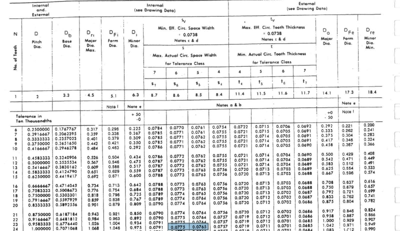
@spigor I was looking at your plots again, may I ask what was your tooth thickness at pitch diameter and pitch diameter itself for that model? I am getting .0780" and 1.000" respectively. My own model is leaning more towards ANSI 92.1 class 6 standard with .778 and 1.000" respectively.

I am trying to confirm some things on my own because it's being sent off to manufacturing. I know your green model fit like a glove with EDM sample I got.
 
I confirm circular space width (not tooth thickness), green plot .0780" at 1.000".
As far as I know, ANSI B92.1 24/48DP 45PA Class 6 has Max. circular space width .0775, so outside the tolerance and would indicate Class 7 with Max. circular space width .0791.
 
@spigor right circular space width not thickness. Would it safe to say the green plot isn't following the standard at all then? Or could it really be class 7 and just worn out a bit, thus skewing the results? I am not sure what to do here and wish I noticed this earlier. I was hoping to put a standard on the drawing then manufacturing has something to go off of.
standard_abmvfl.jpg
 
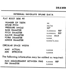
I should also say the drawing has a table of:

Module
Number of Teeth
Pressure Angle
Circular Space Width
Major Dia
Minor Dia

Then under that it says: "Spline Standard in accordance to ANSI 92.1-1996 Table 57 Class 7.

I will obviously send them the DXF file for their reference, along with it in the 3D file on the actual part (igs or step).

I think that will be a enough? They agreed to cut this spline, but I originally told them class 5.

 
What circular space width did you specify on the drawing, .0780? What about the tolerances?
Did you specify any tolerances for the major and minor diameters?
If you got this standard, you could see what data should be placed on the drawing and that a lot is missing (like tolerances and pin dimensions).
However, you could just specify what spline do you want and that should force the manufacturing to obtain all the data needed from the standard on their own.

You could just specify:
Internal involute spline
ANSI B92.1-1996 (the "B" is important)
Fillet root side fit
24T 24/48DP 45PA Class 7

If your part looks to be worn a bit and could be tighter, go for Class 6
If it could be a lot tighter, go for Class 5, which is the standard and the most probable.

The green plot sits inside the Class 7 tolerance field, as measured on the part. Again, check the part for tightness with the mating part.
 
@spigor I never got to EDM the pink one you made or the class 5 according to B92.1-1996 I made. All I got to confirm was the green one you made fit well, how tight not sure because my business partner in a different state felt it out. I know I do not have all info in that table and sorry I should've been more clear on my issue.

.0780 class 6 (reference below). I thought class 6 was a good in between based on the .0780. However, I'm just worried because, again I am not even sure this green spline follows the standard anymore? The green spline had no fillets from what it looks like? Is it a Flat-root, major diameter fit? I'm probably complicating/overthinking this entire scenario because obviously there is a radius on the male root and it fit well, very little play/backlash.

Here is what I have:

spline_info_p99gfc.jpg


123_f9ahth.jpg


I should note, our manufacturer will be doing design verification for us, but I'd like to hit it right first try and not waste money, hence why I'll just provide them the dxf file.

Again, thanks for the help and insight spigor.
 
Hi Speedracerfast
I recommend to let the gear shop reverse eng this spline for you.
The cost required is very reasonable
For a peace of mind.
Except if you can go there with the part and enjoy the tour.

A bit about splines
Splines are verified with spline gages.
For external , max effective tooth thickness is verified spline ring gages.

The internal min effective size is verified
With spline plug go gage.
Max and min effective can not be verified with pins.

So the spline verification will be with
Mbw or mow for actual min and max tooth thickness for external spline.
Min and max tooth space for internal spline.
All classes have the same min and max effective size so it will all assemble.
The tighter classes have less back lash.
For tighter requirements.
 
@mfgenggear right. But out of curiosity is my though process right? class 6 seemed good in between from what I know with backlash per business partner's provided insight/info... but what you're saying makes sense: there isn't a concrete way to know with the way I have gone about this.

We have some internal spline gauges at work (we need them for first article inspections).. doubt we have what I need. I hope there is someone local to me with the setup. Most likely in CA. hmm.

Can you elaborate on the acronyms mbw or mow? I can't decipher .. probably due to lack of sleep YIKES.
 
Measurement between wires
Measurement over wires.
What general area are you in ca
Gear mfg is a small nitch
I can maybe recommend a shop.
 
Also an example
An external spline can be shaped or Hobbed
And be over sized on the max actual tooth thickness mow, as long as it does not exceed the max effective size.
Yet it will accept the go gage.
That means that spline is almost perfect.
The gage will verify total index error,
Involute error, lead error, and size.
When making one or two parts, and no gages
Then it can be inspected to mow, and analytical inspection of the individuals spline tolerances. Mow, lead, involute
Total pitch error, an so on.
But with out gages there is an over tighten of tooth thickness size.
A gage gives more tolerances.
 
Hands down the best way to reverse engineer a gear or spline is with an involute gear checker. If the correct diametral pitch and pressure angle is obtain it will have a straight involute.
And that spline or gear data is correct.
No guessing.
 
@mfgenggear makes sense but I need to sleep on that info. I'm just confused on your last two sentences there:

"But with out gages there is an over tighten of tooth thickness size.
A gage gives more tolerances."

I am located in Seattle, not CA. I only was mentioning CA because I know my real job sends almost all gear measurement work out to CA. Know of anyone in Seattle or WA area? Google is showing nothing. Worst case I can ask procurement folks at work and see if they can help me out.

Hopefully I can get a quickish lead time as we've already collected $$ for group buy. Our margins are terrible (really really bad.. as expected with something like this) and really only proceeding with this to help out the Isuzu community.

I should also note, the only big company that would take this project was 3D Hubs, and all the of their competitors didn't want to touch a internal spline this small. Granted, I locked in 3D Hub's quote during COVID outbreak when it hit China, which is probably why this project is still active as they gave us a good price and wanted the work badly. Otherwise, the margins were actually negative unless sale price went up significantly. I am still pretty skeptical of the 3D Hub's spline capabilities, because the sales rep didn't know if it would be broached or EDM'ed. If it doesn't turn out I'll send them back. Plus they are going to do design verification with us (i.e send us two sets for us to check prior to maing the rest of the batch). Any thoughts on 3D Hubs? I'd love to get these made by a reputable shop, but with quantity low, the quotes were high! Most shops turned me away.
 
Status
Not open for further replies.

Part and Inventory Search

Sponsor