Eng-Tips is the largest engineering community on the Internet

Intelligent Work Forums for Engineering Professionals

Help Understanding Limit Load and Margin of Safety

Status
Not open for further replies.

Dikuza

Aerospace
Jan 18, 2017
35
0
0
AU
Hello, I'm a mechanical design engineer wanting to expand more into structural stress analysis and looking for some clarification on the determination and use of limit load, test loads, and margins.
My question is what actually is Limit Load and how are Margins calculated? See examples below.

The following information is taken from NASA-STD-5001 (Structural Design & Test Factors of Safety for Spaceflight Hardware):
[ul]
[li]Limit Load is "the maximum anticipated load, or combination of loads that a structure may experience during its design service life under all expected conditions of operation."[/li]
[li]"Design factors of safety and test factors shall be applied to the limit stress condition."[/li]
[li]Margin of Safety calculated by the following equation:
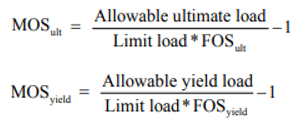
Screenshot_2023-10-13_155854_njsi83.png
[/li]
[/ul]

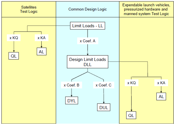
I've also read the European equivalent standard which includes the same definition of limit load and a graphic illustrating factors application:

Screenshot_2023-10-13_160132_s8eou4.png


I have two example scenarios for which I'd like to understand what is what.

Example 1
A human-rated habitable pressure vessel is pressurized to a maximum 15 psi and proof pressure tested to 15 x 1.5 x 1.05 = 24 psi, where 1.5 = proof test factor from nasa-5001 and 1.05 = unknown environmental factor.
From the above documentation, qualification and acceptance test loads are the product of the limit load and test factors. In this example then, it would suggest the internal pressure of 15 psi is the limit load. This, however, in my mind is the "applied" load, and the resulting or calculated stress will be much higher than 15 psi and dependent on material, wall thickness, shape, etc. If I were to determine the margin in this example, it would seem the more appropriate equation would be:
MOS = (material strength / calculated stress * FS) - 1
So what is the limit load, MOS, and allowable here?

Example 2
Very similar to the first example, but more general.
Let's say a cantilevered beam is loaded at its free end by a load P. To test the beam strength given a FS of 1.5, you would load the beam to 1.5xP. Simple. Is "P" here the Limit Load since it's the maximum anticipated applied load and what is used to determine test factors? If so, it doesn't make sense to use this in the calculation of MOS. MOS equation has to include the resulting/calculated stress, otherwise would be independent of the actual structural design which of course doesn't make any sense.

What am I missing here?? Any feedback is much appreciated!
 
Replies continue below

Recommended for you

I won't discuss your particular examples, but I will provide some general information.

You can think of limit load as the highest "actual" load the part will ever see. To ensure the part is safe at that load, we design it to the ultimate load, which is the limit load times a factor of safety (where the FS is often, but NOT ALWAYS = 1.5) So, in that sense, the ultimate load is a "fictitious" load that you design to in order to ensure safety.

You also have to consider the design criteria, which in aerospace usually says something like: 1) no excessive yielding or detrimental deformation at limit load (or perhaps 1.15 times limit load) and 2) no failure or collapse at ultimate load. The Margin of Safety is a measure of how close you meet both these criteria. So you would have a MS for both requirements (1 - yield, and 2-failure). A margin of safety of zero means that you meet the requirements.

You also mentioned material properties and part dimensions, and uncertainties have to be considered for these as well. Some ways this may be done are:

For material strength "allowables" we use MMPDS (MIL-HDBK-5) for values like Ftu, Fcy, etc. These are not "average" or "nominal" values, they are statistically reduced values derived so that most real specimens fail at higher loads. "A-basis" allowables are lower and used for more critical structure (say where a single local failure would lead to a total catastrophic failure), while "B-basis" values are a little higher and used for redundant structure (that is, where is a local failure occurs, nearby structure picks up the load). In any case "allowables" are not average values we get from a vendor or our own in-house tests. MMPDS discusses the requirements to develop allowables. For new materials, this is a big and expensive job.

For dimensions, you have to account for manufacturing tolerances in some way. Say your nominal thickness per the engineering drawing, is 0.1", but the machine shop has a tolerance of 0.01", then the actual thickness may be 0.09" and the part will still be deemed acceptable. Therefore, you may have to base your stress analysis on the 0.09" thickness to be safe. You may not always have to design to the lowest possible thickness though. For example, JSSG-2006 (which you should be able to find on the internet) says in section 3.10.5 that "All structure shall be design to nominal dimensional values or 110 percent of minimum values, whichever is less."

My examples may or may not apply to your application, but I wanted to emphasize that all these questions should be considered together, as a "package deal". And this "package deal" should be clearly documented in the "structural design criteria" for your program. Documenting these criteria should be the first step in any new program, before you build FEMs and start doing analysis on parts. If you don't have one, you should make one!

An excellent book that discusses these, and many other important issues, for space applications is: "Spacecraft Structures and Mechanisms: From Concept to Launch" by Thomas P. Sarafin.
 
@sdm919, thanks for taking the time to respond.
I don't think this really answers my question though.
To put it another way, how can Limit Load be used in the determination of both test loads and design margins?
If this is the max load/stress the part will see including calculated internal stresses, then it would mean the test loads (Limit Load x test factor) are dependent on the design of the part (material, geometry, etc), which doesn't make sense.
On the other hand, if Limit Load is simply the applied load and not the resulting stress, then it would MOS is independent of the design (doesn't take into account calculated stress), which also doesn't makes sense.
 
Limit load is the applied loading that would give rise to the stress value you have labelled 'calculated stress' in the denominator of Example 1 of your first post.

Limit loads are defined such that they envelope the maximum expeceted in-service loads.

Design ultimate load is limit load with the prescribed factor of safety and special factors applied.
 
@Ng2020, this is what makes the most sense to me. It's a bit misleading then to show the same Limit Load in the calculation for MoS, when this is actually the stress DUE TO limit load...
 
Maybe it's confusing because we're using the word "load" for both internal and external loads. The load P at the end of a cantilever beam is the external load, which causes internal loads and stresses at various locations inside the beam. The MS is written based on internal loads/stresses at the critical locations inside the beam. It is not written using the external load P.

Take your cantilever beam with a single concentrated load "P" at the tip. P is the external load. It causes shear (V) and bending moments (M) that vary along the length of the beam. These V & M values are the internal loads. And at each location, you can use the values of V & M to compute shear (fs) and bending stresses (fb). These are internal stresses.

If the external load P is a limit condition, then the resulting values of V & M are "limit loads" and the values of fs & fb are "limit stresses". Similarly, if the external load P is an ultimate condition, then the resulting values of V & M are "ultimate loads" and the values of fs & fb are "ultimate stresses".

Say for a limit external load P=100 lbs your analysis gives a stress of 50 ksi at the critical location. If your yield FS=1.0 and your yield allowable is 60 ksi, then your yield MS = 60/50 - 1 = 0.20. If everything is linear (which is often not the case) and your ultimate FS=1.5, then the ultimate value of external load is P=150 lbs, and your ultimate stress at the critical location would be 75 ksi. If your ultimate material allowable is 80 ksi, then your ultimate MS would be MS = 80/75 = 0.067. No MS was written using P itself.


Dikuza
If you're writing a margin in terms of loads, call it limit load. If it's in terms of stress, call it limit stress, or stress at limit load.

Strictly speaking margins should be in terms of loads ('by how much can I increase the applied loading before failure occurs'). But most of the time are written in terms of stresses as it's generally a linear relationship between the two.
 
it's the same limit load, but with different factor of safety applied.

Those NASA STD-5001 definitions may be correct in theory, or in a specific application. but rarely have I seen them in practice,

In practice MS_ult = ultimate allowable stress/ultimate design stress -1, "ultimate design stress" is the stress calculated under ultimate loads, often limit loads*ultimate FoS (= 1.5).

Test loads are usually calculated for limit load cases. Applied directly then the test is a limit/proof test. If the loads are factored for ultimate FoS, then an ultimate load test.

"Hoffen wir mal, dass alles gut geht !"
General Paulus, Nov 1942, outside Stalingrad after the launch of Operation Uranus.
 
Status
Not open for further replies.
Back
Top