Continue to Site

Eng-Tips is the largest engineering community on the Internet

Intelligent Work Forums for Engineering Professionals

  • Congratulations KootK on being selected by the Eng-Tips community for having the most helpful posts in the forums last week. Way to Go!

Help understanding this pneumatic connection.

Status
Not open for further replies.

KirbyWan

Aerospace
Apr 18, 2008
583
Howdy all,

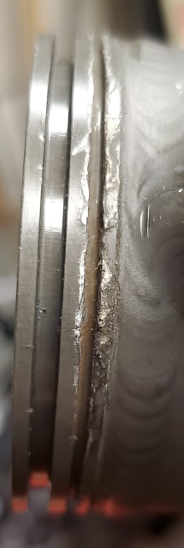
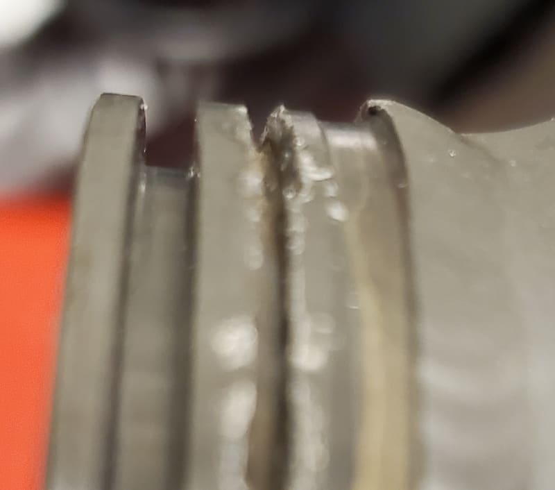
I'm designing the tooling to test a pneumatic motor and I'm stumped by this connection in the pictures below. It's a 2.25" OD with two grooves. The first grove, the larger one I thought was an O-ring gland, but it's a bit narrow at .091 inch and way too deep at .125 inch. The second, smaller groove is just .050 inch wide and .080 inch deep. I designed a connection that "works" using a couple stacked O-rings (size 033) and uses the narrow slot to fit some machined L-angles with bolts to hold the attachment sleeve in place. I'm just not happy with my design and I might make a better connector if I knew how this connector is supposed to work. This is for the pneumatic actuator motor on a 747 leading edge flap drive.

Anyone familiar with the mating connector that matches this port?

Thanks,

-Kirby
20220527_152452_em65zs.jpg
20220527_152109_nzjsct.jpg


Kirby Wilkerson

Remember, first define the problem, then solve it.
 
Replies continue below

Recommended for you

My guess is that the narrow groove is for a pin or "U"-clip (essentially two pins) to pass through in order to lock the fittings together.
 
what does the mating a/c part look like ? defined by some hydraulic system part number ?

another day in paradise, or is paradise one day closer ?
 
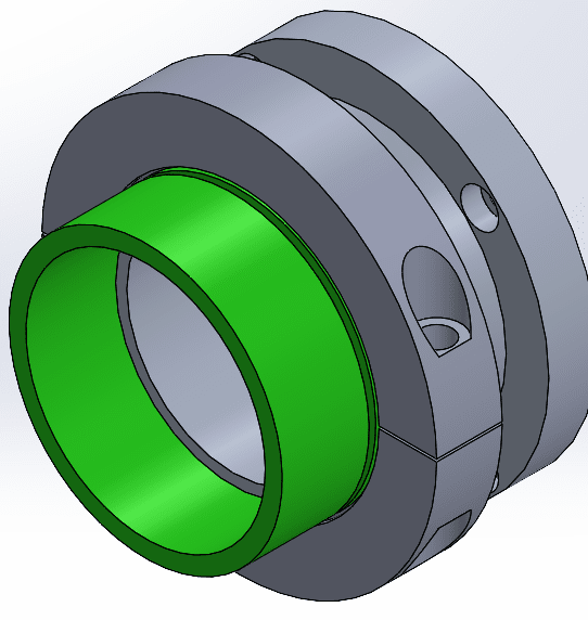
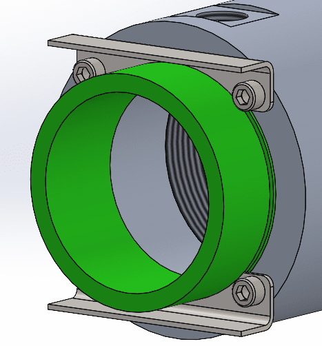
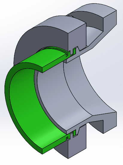
After fiddling with my parts I came up with a small modification to my design that made it workable. I originally was just going to use these bent clips to hold it in place, but after the machinist gave me the parts (and before I gave it to the tech to use) I tried installing it and there just isn't enough space to screw in the bolts. (green part is a model of the connector.) I slotted two of the holes so I could have the fasteners already installed and then just pivot the brackets into the slot and give the fasteners a quarter turn and it should work.

I think if I was going to do this again I would fab the mating part to receive a flat 'U' shaped bracket that goes in the narrow slot like Compositepro was thinking of.

rb1957,

I wish I knew, that was my original problem. like there's a plan to hook this is up and I don't know what it's supposed to look like. It's 46 psi air.

Thanks all,

-Kirby

Screenshot_2022-06-02_130942_xcu7ag.png


Kirby Wilkerson

Remember, first define the problem, then solve it.
 
We're is the O-ring? How would you assemble the coupling in the coupled case? I meant a U-clip where the pins go through clearance holes in the mating part, parallel with the groove, and perpendicular to the coupling axis. Like the pin on a hand-grenade.
 
That second narrow ring looks very beaten up though.

The top picture makes it look like the are three rings but the second one only two rings?

Remember - More details = better answers
Also: If you get a response it's polite to respond to it.
 
The abuse on the edges of these grooves is terrible. These parts may be out of damage limits. Check the SRM/CMM before investing time in making mating pieces if they're already scrap.

The first groove looks too deep for o-rings but the service may be too hot or move too quickly or too little lubrication for O-rings to work there anyway. If it still needs to seal, then something akin to a piston ring may be what you're looking at.

Why the heck don't you know everything about this assembly down to the seals, packers, fasteners and mating parts? Don't you have a CMM? If there is any hope of reassembling this actuator and recertifying the repaired unit, then it should be safe to assume that you're working with a component overhaul shop with the requisite tools and repair data to deal with this. From that, I can infer that somebody is NOT in the dark about how this part works, so you should find them and have a chat.
 
LittleInch,

There are two grooves that you can see in both pictures. The third groove-like feature is just the machined stub of the fitting which in the second picture is mostly covered by weld bead.

WindWright,

This is the part we have in and what we're looking at is the opening where it connects to the aircraft. I don't have the aircraft (a 747), so I can't walk over and look at how this connection works or what the mating part is. I could try and find the AMM which probably has details about installation and removal, but all I have is the CMM which doesn't detail external parts. So my point in posting here is to ask if people are familiar with this type of connection and clue me in as to how it works. This is a new repair part development, so we're learning it.

As to the damaged edges of the groove, I think this groove is used to hold a retaining clip which is why it gets dinged up. The damage is less than .005 inches and we will ensure it meets the CMM airworthyness requirements before we certify it.

Thank you all for your feedback.

-Kirby

Kirby Wilkerson

Remember, first define the problem, then solve it.
 
All speculation. Some initial sealing device (tool) to aid in applying sufficient force to allow proper ease of installation of U clip as suggested by Compisitepro. Without tool, I imagine efforts to hammer the locking U clip into position. Removal of U clip under stress requires screwdrivers, punches or chisels. Damaging unit as seen. Good luck
 
 https://files.engineering.com/getfile.aspx?folder=3fe54472-35ec-434e-a631-0e6907c7d5ed&file=IMG_1546.jpg
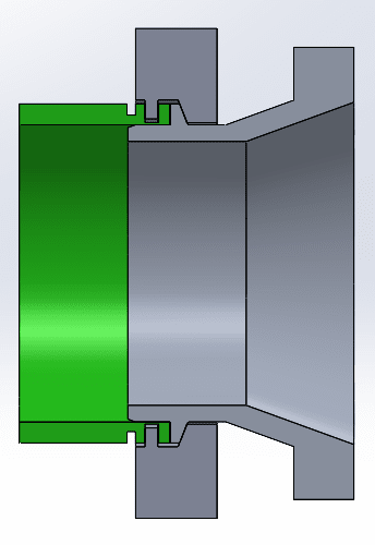
Thanks for the sketch moa1. Someone found a mating part that was used for testing on a different stand and it looks like half a V-band clamp that presses against the face with a couple of blocks that clamp around giving a tight fit in the larger slot. See the pictures. This seems like a much better design then what I had. Here's what I came up with.

-Kirby

Screenshot_2022-06-16_110253_kelnw0.png
Screenshot_2022-06-16_110340_bwxn0f.png
Screenshot_2022-06-16_110409_jczubv.png


Kirby Wilkerson

Remember, first define the problem, then solve it.
 
Status
Not open for further replies.

Part and Inventory Search

Sponsor