Eng-Tips is the largest engineering community on the Internet

Intelligent Work Forums for Engineering Professionals

Help with a residential framing issue 4

Status
Not open for further replies.

Bhotar3

Civil/Environmental
May 6, 2013
62
0
0
US
Contractor friend was hired to finish the construction of partially completed home, after the original Contractor walked off the job. Following a permit inspection, one of the workers had some concerns about some shifting-out of the top of an art studio exterior wall following a wind event.

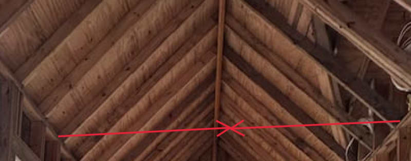
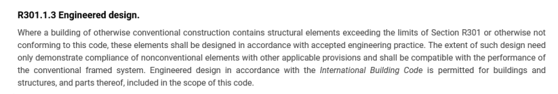
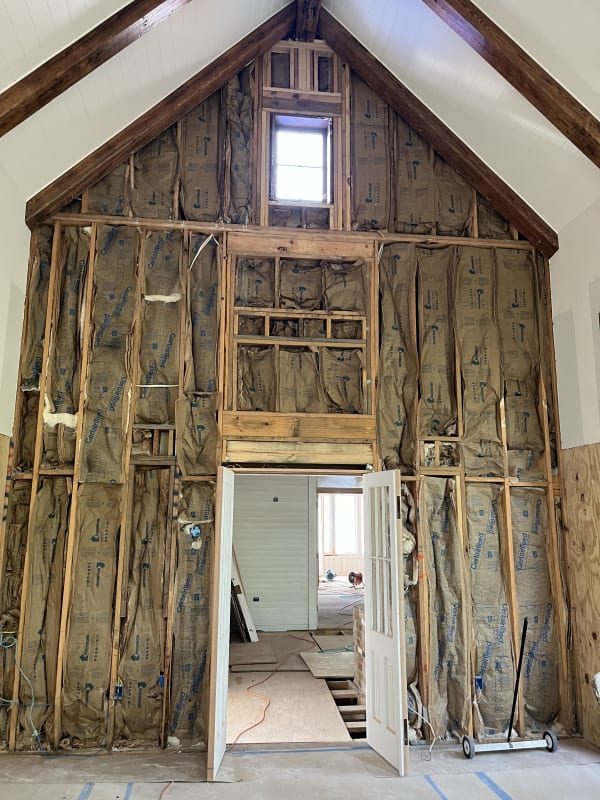
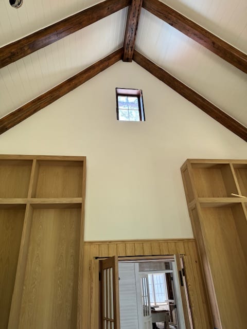
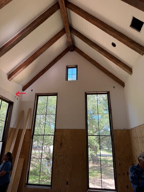
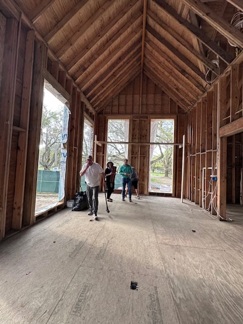
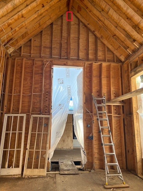
The room is gable framing, and the ridge beam is two 2x10" LVL beams. The ridge beam span is 25'. The pictures attached show the room shortly after framing, and in its existing condition.

I believe, after it was framed, they cut the ridge beam supports and added this 6"x10" cypress beam and these "decorative" 6x6 cypress rafters that are simply bolted into the wall top plate and into the ridge beam.

My belief is that the original ridge beam (two 2x10s) is undersized, and the room isn't adequately braced laterally. After running the numbers, I think the ridge beam should have been 3-ply 2x16. They were wondering if they could post-install the new ridge beam under the 2x10 ridge beam and then "wrap" it with cypress to make it appear like a beam. My issue with that is I'm not sure how the rafters will tie into the new ridge beam or how it would be braced laterally.

My initial 3 options were:
1. Remove 2x10's, replace with 2x16's (Most intrusive solutions because it would take a significant rebuild)
2. Add collar ties for lateral support.
3. Exposed Cables from wall top plate to wall top plate.

Anybody have thoughts here?

IMG_9038_qmp2df.jpg
IMG_9039_qqrdsm.jpg
IMG_9040_w3dbll.jpg
IMG_9037_v2kiww.jpg
 
Replies continue below

Recommended for you

There is a large horizontal thrust at the bottom of those roof beams framing into the ridge beam. This has to be resisted. A horizontal tie rod may be required. You should contact a local struct/civil engineer ASAP for guidance. Something like this at each rafter... or design top plates like a horizontal beam...

Clipboard01_hoo1ja.jpg


-----*****-----
So strange to see the singularity approaching while the entire planet is rapidly turning into a hellscape. -John Coates

-Dik
 
That thrust is questionable, there's supposed to be a ridge BEAM there, that's the LVL, not a ridge board. Beam should be sized to support the roof rafters.

The spreading you may be seeing is potentially at least partly from downward deflection of the ridge beam, if inadequate, and the end wall has a hinge condition (the studs aren't continuous up to the roof rafter, and the header for the post supporting the ridge beam might be inadequate as well. That mid-height spreader/header is another thing.

I don't get what's going on in the right side of those photos, is there a sloped rafter going into another interior space?

Unless they can locate existing sealed plans from a structural engineer, this whole project is pretty suspect.

This post is just in time, join us over here for a similar thread......
 
There is a large horizontal thrust at the bottom of those roof beams framing into the ridge beam. This has to be resisted. A horizontal tie rod may be required.

Yes, with the current ridge beam there which is why I mentioned that in order for them to keep the current cathedral ceiling configuration, the ridge beam would need to be upsized significantly. Do you agree?

My initial calcs told me 3-ply 1.75"x16" LVLs.
 
Something makes me doubt this was all engineered before, this looks like field improvisation in a less regulated area.

If you have a legit ridge beam, which takes half the tributary load for the roof into the end walls at each end, there shouldn't be much thrust (zero in a first order analysis) beyond what develops incidentally due to the downward movement of the ridge beam and the rafter connection to the outward wall. Depending on how stiff the nailing is, that wall rafter may "slip" and the deflection may not show up in the wall (like if there's a Simpson TC24 there). Generally there would be some outward movement as the rafter/wall connection has some strength. This should show up at the mid-point of the wall more than the ends, because the ridge beam should move down the most at the center, some of this deflection (the dead weight) should be/could be "baked in" depending on how they nail or when they nail rafter to wall top plate.

It's possible the ridge beam is okay as is, but like I said, it's not been engineered unless you can find a design drawing, and even so, if you're acting as the "replacement" structural engineer, it isn't like you can just "buy" the original design, you have to produce sufficient calculations to justify it being adequate per your own criteria and analysis. You may also want to check uplift and then unbraced length can influence things. Given the length, C[sub]L[/sub] and C[sub]v[/sub] may have some influence even for gravity.
 
Something makes me doubt this was all engineered before, this looks like field improvisation in a less regulated area

It was def not engineered before construction. The entire house was designed by a “designer”. Not even an architect. I was called in the final hour.
 
Sounds like you should run far, far away from this mess.
Are they going to pay you to engineer the entire thing? (If so, make them pay you in advance).
You likely will need to have the interior finish fully removed so you can figure out what the framing actually is. I would not rely on the photos.
 
Original 10 inch ridge "beam" (yeah right) was drastically undersized for a 25 ft. Gable end walls are also crap because the studs are discontinuous at the stacked plates, resulting in a hinge for out-of-plane loading, like phamENG said.

This was obviously not engineered originally, which it should have been assuming this construction is regulated under the IRC, which requires anything outside the limits of the prescriptive code to be engineered. Vaulted ceilings like this are outside the limits of the prescriptive code.
 
One could potentially just fire off a letter to the AHJ and let them throw the hammer at it.

Our (engineering) duty is to protect the health, life-safety and welfare of the general public, not try to wedge our way into a dispute and fix all the issues on spec. You can flag all the known issues and point out a competent licensed professional engineer familiar with wood construction needs to review the structure for all appropriate loads. You don't have to prove it fails, you should be able to say what is outside the appropriate code (IRC) and that it needs an engineered design per R301.1.3

R301_engineered_design_wzsil7.png
 
Wow, Echoing the other posts on here, your friend has been given a shaving cream sandwich. From a professional standpoint, I agree with running the other direction, but I have also been in similar situations were all you want to do is help your friend make the best of a bad situation. All of your solutions may improve the existing known issues but do nothing to address the underlining issue, being that this is not code compliant, and no supporting engineered design exists. Your friend is assuming that liability for what are likely additional issues down the road.

One option is you help your friend communicate to his client what issues they are and can be facing in the future. Then let the customer decide whether or not to keep your friend hired on and consult an engineer willing to step into this professionally, which will likely be very costly. My guess is, based on your description of lack of local code enforcement, the customer will find another contractor willing complete this but, in the end, you will have helped your friend dodge a bullet.

Second option, help your friend. As previous posters have said on here, if you are providing or even effecting the design and calculations, regardless of whether this is being done on the side, you are assuming most of the liability. Most courts will view this as such since you are the professional and even though your friend may not want to throw you under the bus, under oath, he will be forced to do so. I used to have a coworker, SE/PE who people were always coming to for advice for situations like yours and something he was excellent at doing was pointing the person where to go and let that person make any required judgement calls or calculations. In other words, providing the answers without actually providing the answers. From a professional standpoint, I would recommend that any advice and guidance you give your friend in done in a like manner.
 
Me said:
Those little windows at the top were framed in later?

It looks like this question was accidentally answered in a separate post. But since the answer is yes, it could be that they cut out the posts supporting the ridge beam and didn’t restore that load path around the new windows. Just something to consider.
 
Do you guys think there’s a working solution that might include anchoring tension cables to each wall parallel to the ridge beam, for lateral support?
 
I've had to fix this kind of gable wall before, it required cutting out the king studs on the interior sides of those large windows. Extending full height continuous studs (of whatever size required to work) to the roof level. Blocking that reaction into the roof framing. Connect the existing mid-height double plate to these full height studs so they act as wind beams.

I also have concerns for what framing is over the tiny window. It doesn't show up on the original framing photo of that area.
 
The solution mentioned above would certainly work, but I would also consider running a beam horizontally above the windows to resist the wind load. This might be a more efficient design considering the wall appears to be much less wide than it is tall.

This may require a deeper beam than the current wall depth, but such is probably the case with new full height studs anyway. I usually end up with 2x8 framing in walls like this.
 
Status
Not open for further replies.
Back
Top