Eng-Tips is the largest engineering community on the Internet

Intelligent Work Forums for Engineering Professionals

  • Congratulations waross on being selected by the Eng-Tips community for having the most helpful posts in the forums last week. Way to Go!

Help with choosing right type of gear 2

Status
Not open for further replies.

JerinG

Mechanical
Oct 18, 2009
99
SI
I have to detail a gear transmission in which positions and orientation of both gears were already chosen. I can't change axes angles beacuse some parts to which these gears are mounted were already made. Outer dimensions of gears are also fixed because of gear ratio.

I need help with choosing a right type of gears. I've attached a STEP file of gear pair. Maybe someone with more knowledge and experience with gear desigh will quickly see which type of gear should I use. I was thinking that I should use straight or spiral bevel gears. Crossed helical also came to mind but after closer look it looks like it has to be beveled.
Thanks for help in advance.
 
 http://files.engineering.com/getfile.aspx?folder=91510504-a5e6-47ee-9453-8cdcce5f33a0&file=17005-0005_Gear_drive_assy.STEP
Replies continue below

Recommended for you

The gearing you're after is generally called 'tapered spur' or 'tapered helical'.
The correct terminology is 'beveloid'.
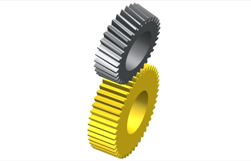
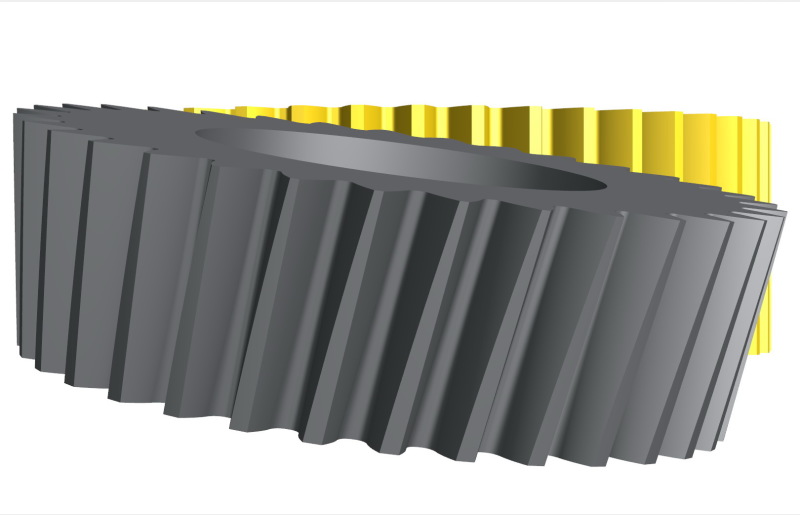
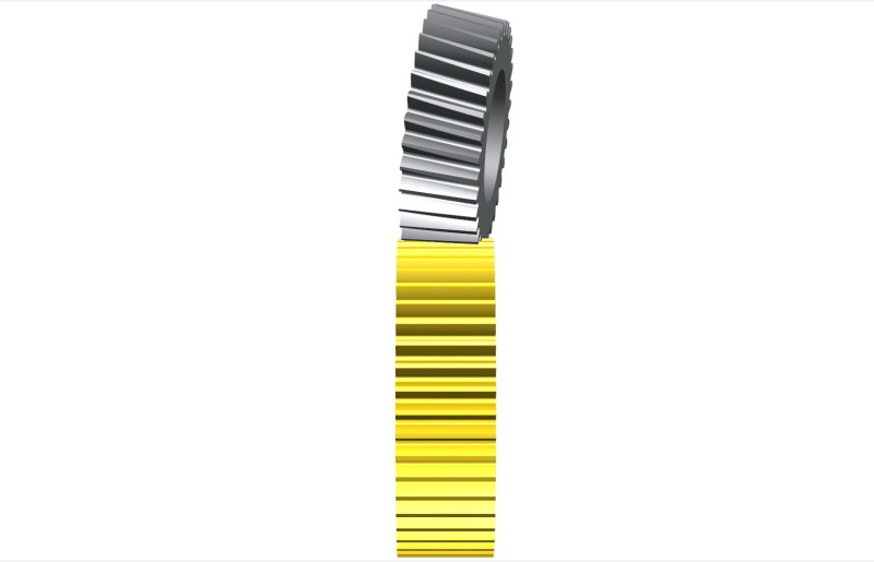
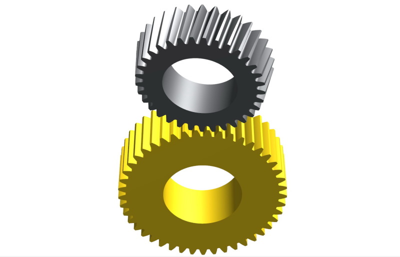
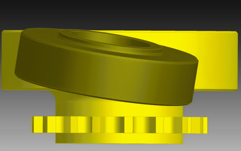
In your case you need a spur gear that meshes with a tapered helical.
The example below shows a set where the shaft angle is 10deg and the cone angle of the pinion is 7deg.
These gears are easy to manufacture. Most shops will do them, especially if they have CNC Hobbers.


2.25m_45-33_04_xpasyp.jpg


2.25m_45-33_03_ckjkj0.jpg


2.25m_45-33_02_kkrhi7.jpg


2.25m_45-33_01_rob9u9.jpg
 
That is one weird V-drive.

Do you need another set, opposite hand, for the other engine?


Mike Halloran
Pembroke Pines, FL, USA
 
That's great. Thanks for answers. Thanks also for posting the image.
Yes, I need a two pair of these sets, one is mirror. Need for this comes from using existing cylinder head for valves and new made crankcase. One more question. Can someone point me to some good (and practical) literature about these beveloid type of gears. Spur gear is not such a problem, but beveloid is new area for me. Maybe such literaure that shows calculation of gear geometry and also has some pointers about final drawings for gear production.
 
I am curious why was this design chosen, it seems very awkward. all though as gear cutter states it's manufactured by some, it not very common in our shop. and it will take full cnc to cut & grind, depending on the AGMA class required.
 
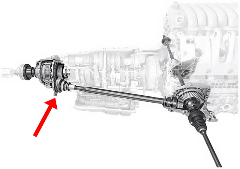
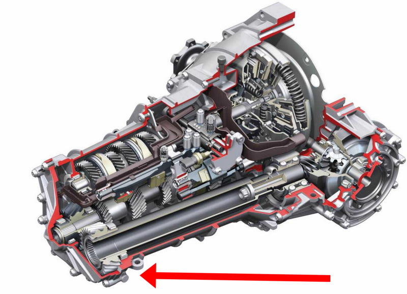
Beveloid gears are quite common, although I'm not sure what the 'V-Drive' is that Mike's referring to.
The examples below are from Audi & Porsche.
I've also seen these gears in stern-drives of boats and, would you believe, in the drive of a 1930's-built rotating platform for steam locomotives.

1264-web_1_bi7a5x.jpg


audi-manual-transmission_1_qj2nxn.jpg
 
If you just mesh a standard helical gear with a spur gear you get a skew gear:
It will only have a point contact and therefore limited power transfer capability.

It is possible to make beveloids to have a decent contact pattern and power transmitting capability, but it is not easy. It used to be done with trial&error in the past with some success, but only the advent of Loaded Tooth Contact Analysis software has made it possible to design and develop the gears the gearcutter is showing us.

If you combine the two, you get all the issues combined, as well as some new issues...

If your application is a real world thing, you should be awared it won't be easy. Here is how it has been done with the beveloids:
 
It's real world thing. I have a customer who is working on new type of engine and he has most of the parts for the engine already made. The original designer of the engine made the draft of valve drivetrain and now I have to detail it and put it to life. Mostly I have common spur gears in drivetrain. Only pair that is different is this one. As I mentioned, the angle comes from using cylinder heads from other engine. Plane on which whole chain draivetrain for the valves lies on is inclined toward other part of drivetrain and that's the part where this pair of gears is used.
Good thing is that these gears don't transmit a lot of moment. But they can have large rpm.
I have to find the most simple solution that will also work (as always). But I have a lot of limitations that I have to consider, because as I already said a lot of parts for the engine were already made. Parts that define angle in this gear pair were also already produced.
I will check literature you provided and if someone gets any other idea, please let me know.
 
A camshaft drive transmits more torque than is first obvious.
Worse, it comes in pulses, as each individual cam lobe pushes its respective valve open.
Even worse than that, the valve tries to drive the cam forward as it closes, so the cam drive is subject to reversing torque. ... which is not real good for the gear teeth.

Do you have access to the original engine designer's calculations? There may be some hints therein that will save you from a few development dead ends.


Mike Halloran
Pembroke Pines, FL, USA
 
How about using some kind of flexible coupling or even a joint?
 
I don't have access to original calculations so I'm on my own here.
I just have rough design with gears shown as cylinders in CAD model. Except sprockets are shown more detailed. From this I have to detail it and make technical documentation.
I thought about some coupling also, but it would be hard to bring it in original design of drivetrain. Would have to change too many thing that I can't afford to change.
 
Sounds like it might be time for you to engage the services of a gear-design consultant.
 
I will contact few of gear manufacturers in my country and then I will see. When I know more I will post again. Thanks for now.
 
The arrangement of gears and chain sprocket shown looks like there might be some difficulty with things like support bearings, timing adjustment provisions, etc. Have you considered all of these issues with this design?
 
All these issues are solvable. As I said it is a engine prototype and cylinder heads from some other engine are used. If this engine will ever go through further development, cylinder heads will also be developed and angle in this gear pair will probably be removed from design. Thanks for heads up, nonetheless.
 
I love a happy ending. Thanks for the photos.


Mike Halloran
Pembroke Pines, FL, USA
 
Status
Not open for further replies.

Part and Inventory Search

Sponsor

Back
Top