Continue to Site

Eng-Tips is the largest engineering community on the Internet

Intelligent Work Forums for Engineering Professionals

  • Congratulations GregLocock on being selected by the Eng-Tips community for having the most helpful posts in the forums last week. Way to Go!

Help with gearing, torque & hp numbers 1

Status
Not open for further replies.

eherna13072

Industrial
Nov 20, 2019
6
Hello, I finally caved in and I am asking for help since these forums seem to be very knowledgeable. I am not a mechanical engineer, I am just a industrial technician. I am currently working on a project on a piece of equipment we call a "Locomotive" which basically is a huge piece of equipment that contains stuff for the manufacturing process. It sits on wheels that sit on rails and is moved back and fourth every shift for cleaning. So currently the gearbox is obsolete and the over torque protection no longer works. The gearbox was easy but the over torque has no numbering. I am trying to figure out if my numbers match from reverse engineering. I also want to know if HP stays the seem through changing of gearing and sprocket size. I know torque can go up and down but does HP? RPM from the motor stays constant but RPM from size of sprocket changes, so does that also affect hp?

Current State:(if HP is constant)
Motor: .75hp/1725rpm shaft 5/8" w/ 3" pulley (27.4 in/lbs)

Gearbox: 100:1 (Input) shaft 5/8" w/ 8" pulley (72.96 in/lbs)(rpm 646.88)
(Output) shaft 1.5" w/ 5.52" Sprocket 26 teeth (7,296 in/lbs)(rpm 6.47)

Drive shaft: shaft 1.25" w/ 8.715" Sprocket 42 teeth (11,783.04 in/lbs) (rpm 4.0062)

Hopefully these numbers are accurate?

Currrent Over torque protection(OTP)- is on the gearbox input side. Its the 8" Browning pulley with seems to be clutch material. What I found that looks similar is a "Morse Torque limiter Models 250A and 350A" and that is inside the pulley. This usually fails and breaks the driven chain on the output side.

Future state OTP: I am wanting to put OTP on the output side of the drive shaft, which is why I would like my numbers to be accurate.

any tips or help would greatly be appreciated.
 
Replies continue below

Recommended for you

Hi

The HP normally stay constant and the torque changes with the inverse of speed, I haven’t time to check your numbers but will later.

“Do not worry about your problems with mathematics, I assure you mine are far greater.” Albert Einstein
 
Download the Cowern Papers

Go to the section entitled "Understanding Torque"

This is a great reference and is not overly technical. It will provide you with a lot of useful information.
 
Hi

I have checked the rpm speeds and they look okay but not sure where the drive shafts fits in , have you got a sketch of the setup

“Do not worry about your problems with mathematics, I assure you mine are far greater.” Albert Einstein
 
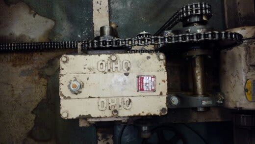
1548349498540_wm29ds.jpg


This is the current set up. The driven side of the gearbox. The "drive shaft" is what I call the shaft that actually moves the locomotive chain.

I was working on the drive side, that is why there is nothing there. (bottom of pic)
 
Hi Again

I will post later today thanks for the pics


“Do not worry about your problems with mathematics, I assure you mine are far greater.” Albert Einstein
 
Hi
I agree with your figures for torque and rpm, that said the figures don't allow for any transmission losses. why do you want to put OTP on the output side of the gearbox?

“Do not worry about your problems with mathematics, I assure you mine are far greater.” Albert Einstein
 
Consider using a v-belt to input motor power to reducer input shaft. If an over-torque condition occurs the belt slips, or if the v-belt is intentionally undersized, it would break.
 
Desertfox thanks for the feedback, at least I know my simple math skills aren't that bad. The reason for OTP was in my eyes, to stop the input to the driven chain, which is the weakest link. The smaller double chain that's connected to the drive shaft (top of the pic) is a 40-2 that would constantly break. This is mostly due to the worn out OTP on the input side that isn't really functional anymore. My plan was to use a magna drive coupling as OTP. Due to it have minimal maintenance once setup properly. This drive system is in a hard to reach location, so a chain or belt breaking makes this difficult to have to repair when there is production running. Also having to adjust a clutch type OTP will most likely cause more downtime if it starts slipping during production. Do you think this idea is a mistake?

dvd - That sounds like a good idea, right now its a right now its cogged/toothed belt. Which I am guessing is because of the clutch style pulley. Which I want to get rid of.
 
Hi

Well I wouldn't put OTP at the driven side, you need to find out why the driven side is failing,i.e. It might be fatigue and not overload. It late so I will post more tomorrow


“Do not worry about your problems with mathematics, I assure you mine are far greater.” Albert Einstein
 
Hi

The over load protection closest to the motor is in the correct place in my opinion because if the motor generates a fault and produces two or three times nominal torque the OLTP protects the gear box if you put this on the other side then the gear box will see the torque over load.
To me any over load torque would come from the motor side because its the motor that generates the torque, now if you are over loading the locomotive with whatever it is doing then the motor generates a torque to match, then as a consequence of over loading the locomotive the weakest component fails. So you need to start with the locomotive and calculate backward what size motor you require to move the locomotive and then size the gear box etc to that figure.

“Do not worry about your problems with mathematics, I assure you mine are far greater.” Albert Einstein
 
It seems like anywhere an OLTP is placed it will protect the system as there can be no torque without an applied load.

That said, I'd suspect that placing it at the motor will require the smallest device as that is where there is the least torque. As long as the OLTP is reliable, easy access is not required, but placing one in an easy to access location, subject to higher torques/a larger device, may satisfy the peace-of-mind requirement.
 
Hi enerna13072

Perhaps another way to think about what you are doing is to ask:- what torque over load figure will you set the protective device at if you put it on the output side of the gear box?

Now your calculations show under normal working conditions the maximum torque output is 11,783 in-lbs, this doesn't mean that you are getting this torque figure when the locomotive operates, it means that's the maximum it can see under normal operating conditions, the actual torque could be anywhere between maximum and minimum. However the electric motor will normally have an overload factor which might be anywhere between 1.5 to 3 times normal rated torque.
So lets say the locomotive needs more than the 11,783in-lbs torque to run with a particular load,lets assume two times maximum torque so 23,500in-lbs is required, provided the motor and gearbox is rated for two times the normal load torque along with the rest of driving mechanism then the system will still operate, unfortunately the torque requirement above might well exceed the design torque of some of the components within the current drive system and hence the failure/s.

It would be better to work out the torque you need at the locomotive and work backwards through the gear box and eventually to the electric motor, only when you know the actual torques you need will you be able to select torque limiters correctly which ever side you mount them on.


“Do not worry about your problems with mathematics, I assure you mine are far greater.” Albert Einstein
 
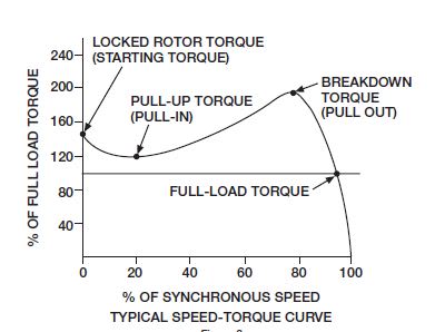
Unless the motor has some type of soft starter, it will exhibit the characteristics shown below. So be careful about sizing over-torque protection. Is it possible to install a soft-start of some sort - RVSS, VFD, etc?

torque_curve_ffptxv.jpg
 
Thanks everyone for the input. Very helpful and made me rethink of the design. I will go ahead and add the OTP on the input side of the gearbox,which will be easier to get the 25% of tripping torque.

What have you guys used or recommend? Spring loaded, friction disc style or what other options?

I wish I could add a VFD, that would be very helpful but that would be a "huge" change in the design according to our current guidelines.
 
Hi again

I asked our electrical guy at work we set all our overloads using a VSD so sorry about that.
Can you estimate the mass of the locomotive you are moving?

“Do not worry about your problems with mathematics, I assure you mine are far greater.” Albert Einstein
 
Status
Not open for further replies.

Part and Inventory Search

Sponsor