Continue to Site

Eng-Tips is the largest engineering community on the Internet

Intelligent Work Forums for Engineering Professionals

  • Congratulations waross on being selected by the Eng-Tips community for having the most helpful posts in the forums last week. Way to Go!

Help with Inertia Relief & RBE Issue

Status
Not open for further replies.

Burner2k

Aerospace
Jun 13, 2015
193
Here is the setup of my problem. I have a projectile which is being launched from a tube. I need to do a static analysis on the projectile. Objective is to ascertain integrity of the structure during launch. I have quasi-static loads (in terms of Gs) which the projectile will experience at the time of the launch.

Screenshot_20231105_123138_djloxy.png


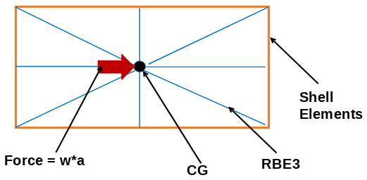
I have modeled the structure will shell elements and have created a node at the CG. A RBE3 connects from the CG node (dependent) to the shell elements (independent). I am the acceleration as a force (mass x g) on the CG.
Screenshot_20231105_123209_lfwash.png


Trying to do a linear Static Solution (101) using Auto Inertia Relief. The issue is that NASTRAN wants to apply balancing accelerations on the CG itself and since NASTRAN does not allow RBE3 dependent nodes to have any SPCs, I am getting Fatal Error messages.

Since Inertia Relief does not support Grav cards (actually it doesn't give any errors but only zero deflections), that option is also ruled out.

I guess for now, I'll create another node near CG & make that node the dependent of RBE3 & apply my force on that node.

But I would like to hear on alternate approach to accomplish the above analysis.
 
Replies continue below

Recommended for you

is your projectile being constantly accelerated ? Is there a load/pressure being applied to the projectile ? Or is the projectile moving at constant velocity ?

In any case, I don't think you want to apply the load to the CG as you are. I think you want a "body force", which will load all the masses of your model with your acceleration. Make sure your masses are consistent with your accelerations ... your masses can be weights if your acceleration is in "g", if your model is in inches, then your acceleration is in in/sec^2 and your mass is in "snails" (I think ... the inch equivalent of slugs).

I wonder ... I think you need to apply a load to the face being loaded (like with pressure in the gun barrel, something is applying force to the projectile to make it accelerate) ? react this with the inertial load at the CG, so the body is in force balance, or with a body force (thinks ... that's better). Then constrain the body for rigid body motion (6 dof) ... constrain 1 node in 6 dof, or the classic 3-2-1 translational constraints.

"Hoffen wir mal, dass alles gut geht !"
General Paulus, Nov 1942, outside Stalingrad after the launch of Operation Uranus.
 
Are you modelling the projectile or the tube?
Why are you trying to apply a single force? Why not just apply an acceleration?
The RBE3 is not going to distribute the acceleration induce forces correctly, as those forces are a function of the mass distribution.
 
yes, that's why I thought of a body force reaction to an applied load. Then it's "simply" constrain rigid body motion.

Oh, and a drag load too ... in the barrel ? in flight ??

"Hoffen wir mal, dass alles gut geht !"
General Paulus, Nov 1942, outside Stalingrad after the launch of Operation Uranus.
 
RB1957 & SWComposites,
I am modeling just the projectile (or structure). The tube is not considered here. The objective is to assess the integrity of the structure (skin as of now with layup definiton) under sudden acceleration (NOTE: After the initial instantaneous acceleration...there are no loads). This is just the first cut analysis. No drag loads are considered now (until they are generated or determined).

@SWComposites, I am not sure where to constrain the model. That's why I didn't apply an acceleration load.

@RB1957, I will try iso-static constraints (3-2-1)...and also check out how to apply Body Force in Patran/Hypermesh.

Thanks for the replies as always guys.
 
Isn't that what inertia relief is for? to balance the acceleration induced loads? (admittedly its been decades since I've had to mess with this sort of analysis in Nastran).
 
@SWComposites, in Inertia Relief, I know for sure GRAV cards get cancelled out...probably same is true for Accelerations as well. The analysis will run but the output is all zero (zero deflections, zero stresses etc.)
 
Ok, you are correct. IR is for balancing an unbalanced set of applied forces.

So for your projectile - what is the propulsive force? Pressure on the aft end? Can you apply a pressure load on aft surface and react with IR?
 
yeah, but in this case it isn't "relief" but "load".

IMHO, the correct way to model this is to apply the driving force (pressure ?) which results in the projectile's acceleration.
Since you want a static loadcase the applied force is reacted by an opposing body force (acceleration).

"Hoffen wir mal, dass alles gut geht !"
General Paulus, Nov 1942, outside Stalingrad after the launch of Operation Uranus.
 
^^This was a first cut analysis to give us a starting point on our sizing. The contained carries an object which has significant mass.

Currently, I created another node (offset from CG by a small distance) & applied the acceleration as a statically equivalent load (m x a) & ran an IR SOL 101 analysis. The analysis ran and showed us that our current sizing is an overkill.

In the coming iterations, we will be modeling in greater detail as well as realistic loads (pressure).
 
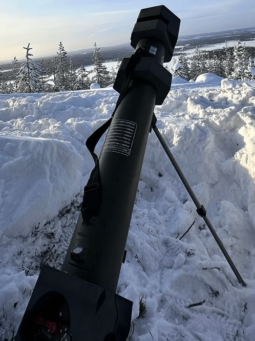
I have a different question but related to the above. Typically, what materials are these tubes made of? At least the contemporary ones? Example of a contemporary system would be Common Launch Tube (CLT)...Composites are a great choice...just wondering if other materials (other than metallic structures) are being used (perhaps newer plastics)?
 
pert near anything that can handle the pressure loads, after that (and a million other design decisions ... environment ? weight ? ...?) it is what is cheaper/easier for you.

"Hoffen wir mal, dass alles gut geht !"
General Paulus, Nov 1942, outside Stalingrad after the launch of Operation Uranus.
 
If the tube is ground mounted, just use steel.
If aircraft mounted, then weight matters, so maybe composite or aluminum or titanium.
It all depends on a lot of detailed requirements- loads, environments, weight, cost, number to build, etc.
 
For the initial set of prototypes, we will be using Aluminum since excess weight is a consideration but not a requirement. Just part of overall literature survey, was curious to figure out what kind of material these types of launchers might be using...

Untitled_cy2vun.png
 
is this a "mortar" with repeated firings (but the legs look pretty spindly) or more of a one time deal ?

metals I think can handle the load spike from a firing better than composites. I think Al (7075 or 7050) are good choices, maybe tailor the thickness to the pressures (but I think this would be a small weight savings, at maybe considerable engineering and manufacturing cost). Are you welding this ? Then maybe Steel would be better ?

"Hoffen wir mal, dass alles gut geht !"
General Paulus, Nov 1942, outside Stalingrad after the launch of Operation Uranus.
 
On the original question of inertia relief, under most circumstances, an inertia relief analysis in MSC Nastran does not have any SPC’s defined. Special cases may arise, for example if you want to study a symmetric half model, in which case the acceleration vector must be orthogonal to the restraints for correct results.

You wrote: “The issue is that NASTRAN wants to apply balancing accelerations on the CG itself and since NASTRAN does not allow RBE3 dependent nodes to have any SPCs” - are you trying to model the restraint that the projectile is guided to move along the axis of the tube you show in the diagram, yet without modelling the tube? In this case an SPC in the translational directions perpendicular to the axis of the tube along with the rotations around these same directions would mean the projectile would only be able to slide along the axis of the tube or rotate around the tube axis.

By the way, you may add an SPC to the GRID point you show at the CG, which is currently the dependent point of an RBE3, but you must either modify the RBE3 to use the UM option, to move the dependent DOF to other GRID points, or you can do it the lazy way and use PARAM,AUTOMSET,YES; this latter option will reorder the independent/dependent DOF in any way it see fit, but it will not change the basic constraint that the RBE3 embodies.

Inertia relief in MSC Nastran does in fact support GRAV and other acceleration loads (ACCEL1, RFORCE,…), but you have to tell the job you want to compute the forces due to acceleration rather than the acceleration due to forces. As you discovered, if you don’t do this, you get a null solution, which is the correct answer for the problem posed. To use GRAV etc. loading with inertia relief, include a DMIG,UACCEL entry, where you can define the point(s) at which you want the acceleration to be some specific value. The code will then compute the forces to establish equilibrium and apply them to the model such that the acceleration at the defined DOF is obtained. See the Linear Static User’s Guide for an overview and example.

DG
 
RB1957 & dmapguru,
Firstly, sorry for the late replies. Last month has been super crazy and super busy for me.

RB, we have decided to go with steel even though that would make our product heavier than we'd like. This launcher would be a ground based system and& a proof of test article and to be on the safer side, went with over-engineer the heck out of it. Plus steel is easier to weld compared to Aluminum and has better HAZ properties.

Dmapguru, thanks for your suggestions. I totally forgot about Um option and I'll look at UACCEL card to get better clarity.
 
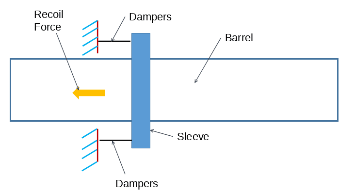
I wanted some tips on simulating recoil force on our launcher. The launch is being done by pneumatic means and considering the pressures we have, the recoil force is gonna be significant. For verification, I want to do a FEA.

The setup illustration is shown below.

Screenshot_20240211_182701_l8l49j.png


Obviously, I've simplified the diagram and omitted a few mini-components. Currently, we plan to deal with the recoil force by using a combination of barrel travel & dampers. I understand the recoil is a dynamic event but I am hoping to do a static analysis for the 1st cut verification. We've calculated recoil force using simple rigid body equations. The material of the barrel & sleeve will be Steel AISI304/316. The solver I'll be using is MSC Nastran.

I am hoping to spread out the entire recoil force on to the barrel using RBE3 MPC. The dampers will be represented by CBUSH elements and one end will be fixed. Does this FEA setup makes sense or am I missing out on something that would be make the setup over simplified?
 
Is recoil "just" the pressure acting on the barrel behind the projectile ? I think you need a dynamic model to determine the ballistics of the projectile, and the concurrent loads on the barrel

"Hoffen wir mal, dass alles gut geht !"
General Paulus, Nov 1942, outside Stalingrad after the launch of Operation Uranus.
 
Status
Not open for further replies.

Part and Inventory Search

Sponsor