Lttlcheeze
Mechanical
This may be simple to some, but this is my first experience with designing gears, so bear with me...
I'm trying to "cut" a spur gear to match the profile of the pinion gear I designed. This gear won't carry any load, it's basically for esthetics, but I want good contact between the two gears.
I have an 8 tooth pinion & 60 tooth spur gear.
Here is my pinion gear:

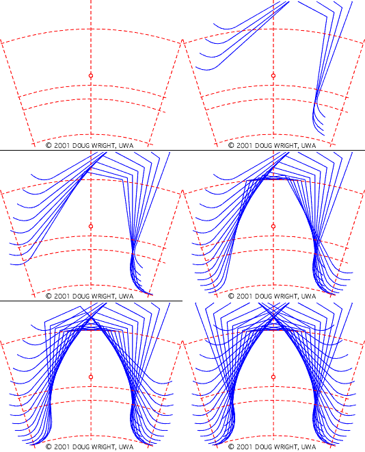
I am working with one tooth profile and trying to simulate it moving out of the mating gear. Seems simple enough...
This is the shape of one tooth, and the line/arc segments are something I drew that approximates what I should end up with (I used the assembly and adjusted the points until it was close).

I could just use those line segments, but I really want to figure this out mathematically.
This is what I figured should be right, but obliviously it's not...
-I drew a circle around the main gear with a radius of the distance between my gear shafts.
-Keeping the center of the pinion gear tooth coincident with that circle I rotated it 5 degrees (I plan on making this increment smaller once I get the calculation figured out).
-Then I rotated the tooth around the center of the spur gear at the increment that it would rotate if the pinion rotated that 5 degrees.
That was .6666666667 degrees. My math:
60 tooth spur - 8 tooth pinion
1 rotation = 7.5 rotations
360 degrees = (360 * 7.5) 2700 degrees
2700 / 5(sketch increment) = 540
360 / 540 = .666666667
I'm sure I’m over simplifying this because here is my result:

The red line is the line/arc that represents where I should be.
I know it's really cluttered, but I figure once I get this figured out I can just use this file as a template.
So obliviously .66666667 is too much of an increment.
Just playing with the numbers I found .59 is really close to what I need. But I don't know how to get there mathematically.

Does anyone know if I'm just completely over simplifying this, or am I doing something wrong in the math????
Please help!!
Thanks,
Bill
Not sure if it will work but I also attached a .gif depicting what I'm trying to accomplish.

I'm trying to "cut" a spur gear to match the profile of the pinion gear I designed. This gear won't carry any load, it's basically for esthetics, but I want good contact between the two gears.
I have an 8 tooth pinion & 60 tooth spur gear.
Here is my pinion gear:

I am working with one tooth profile and trying to simulate it moving out of the mating gear. Seems simple enough...
This is the shape of one tooth, and the line/arc segments are something I drew that approximates what I should end up with (I used the assembly and adjusted the points until it was close).

I could just use those line segments, but I really want to figure this out mathematically.
This is what I figured should be right, but obliviously it's not...
-I drew a circle around the main gear with a radius of the distance between my gear shafts.
-Keeping the center of the pinion gear tooth coincident with that circle I rotated it 5 degrees (I plan on making this increment smaller once I get the calculation figured out).
-Then I rotated the tooth around the center of the spur gear at the increment that it would rotate if the pinion rotated that 5 degrees.
That was .6666666667 degrees. My math:
60 tooth spur - 8 tooth pinion
1 rotation = 7.5 rotations
360 degrees = (360 * 7.5) 2700 degrees
2700 / 5(sketch increment) = 540
360 / 540 = .666666667
I'm sure I’m over simplifying this because here is my result:

The red line is the line/arc that represents where I should be.
I know it's really cluttered, but I figure once I get this figured out I can just use this file as a template.
So obliviously .66666667 is too much of an increment.
Just playing with the numbers I found .59 is really close to what I need. But I don't know how to get there mathematically.

Does anyone know if I'm just completely over simplifying this, or am I doing something wrong in the math????
Please help!!
Thanks,
Bill
Not sure if it will work but I also attached a .gif depicting what I'm trying to accomplish.

