Continue to Site

Eng-Tips is the largest engineering community on the Internet

Intelligent Work Forums for Engineering Professionals

  • Congratulations KootK on being selected by the Eng-Tips community for having the most helpful posts in the forums last week. Way to Go!

Help with my test setup

Status
Not open for further replies.

Rusty Shackleford

Mechanical
Oct 17, 2016
6
Hello. Was hoping you guys could help a poor mechanical engineer out...I’m in need of performing some benchtop verification testing of 1kohm potentiometers rated at 0.5W and some microswitches rated a 125VDC and 10A. While I’ve written test specs for these types of devices before and feel comfortable with the test parameters and methodology, I’m now with a new and smaller employer where I find myself needing to act as the test technician also. I don’t have the hands-on experience on the electrical side nor familiarity with test equipment. Below are details of the test equipment I think I need. Please let me know if I’m on the right track or if I’m doing something wrong or impractical/overly costly. THANKS!!!

For the switches, I need to confirm their switch rating to ensure the contacts don’t burn up. I plan to create a test circuit using a 125VDC voltage source and a (~12.5 ohm resistive load to create a 10amp circuit. The resistive load would obviously need to be rated for 1250W or higher. I plan to use the microswitch to make/break the circuit. Since this is considerable power, test equipment appears rather expensive. I’ve found the following:
• DC Power Supply: GW Instek PSU 100-15 ($2000, 150VDC max output, 10A rating, 1500W)
• 1ohm Power Resistors: TE Connectivity TE1500B1R0J ($65/ea, 1 ohm, 1500W) I’d buy three and need to use 2 or 3
• 10 ohm Power Resistor: TE Connectivity TE1500B10RJ ($65, 1 ohm, 1500W)
Is this a practical way of performing the test or am I spending too much money? I’m assuming the load regulation of the power supply can reasonably keep the output voltage within 120-130VDC as I don’t need stringent test tolerances.

For the pots, I need to confirm they can handle their power rating so I will be applying about 22Vac with the pots at their max setting of 1000ohm. I plan to purchase a variac (variable transformer such as Staco Energy 3PN1010B) for about $500 to accomplish this. Alternately, if I purchase a benchtop DC power supply for the microswitch testing, then I could just use it and not buy the variac.
 
Replies continue below

Recommended for you

How many and how often are you going to be testing? Seems like a lot of infrastructure to do a one-off test of parts that cost a few bucks. Can you get test data from the manufacturer?

TTFN (ta ta for now)
I can do absolutely anything. I'm an expert! faq731-376 forum1529 Entire Forum list
 
IRstuff - we have to perform the testing ourselves as independent verification. I agree, lot of effort for some cheap parts but this is part of a large project worth a lot of money. This scope of the project is actually a drop in the bucket compared to the mechanical side of it.
 
Still, I would ask the manufacturers if they can do the testing, since they hopefully already have the test infrastructure. They could probably test a dozen parts for your test hardware cost alone.

TTFN (ta ta for now)
I can do absolutely anything. I'm an expert! faq731-376 forum1529 Entire Forum list
 
Your first power supply is programmable, so it's unclear whether you really need the resistive loads; you could possibly just program it in constant current mode for 10amp, with a voltage limit at, say, 5volts, but you seem to be missing the digital multimeter for reading the result, unless that's all manual and visual. I guess that's tied to the question you've not answered, i.e., how many parts tested and how often?

TTFN (ta ta for now)
I can do absolutely anything. I'm an expert! faq731-376 forum1529 Entire Forum list
 
IRstuff,
I will be testing 5 pieces of each - it would be impractical to get a manufacturer to do this. I want to keep the conversation focused on the original problem - for me to perform the testing.

I already have a calibrated multimeter - I only listed items to accomplish the circuit and not measurement.

To verify a contact/switch rating, you have to test to the actual ratings or application requirements. Breaking a 5V / 10A load is nothing compared to 125V / 10A. If the voltage isn't 125V, then it isn't a proper test and won't generate the same arc intensity/duration and localized contact heat during breaking of the load. Must break 125VDC and 10amp load. Must be resistive load. Inductive loads for contacts are different (and much lower).
 
Where are you Rusty?
In many places you can find independent test labs that will do this kind of work.
The may charge you $1,000 but they will test to known protocols and standards.

= = = = = = = = = = = = = = = = = = = =
P.E. Metallurgy, consulting work welcomed
 
EdStainless - labs with the accreditation I need are very limited and we would have to audit their QA program first - not practical and more costly than the lab equipment. I would like to focus the discussion on the test setup.
 
Is this a practical way of performing the test or am I spending too much money?

I'd say not. I'd do this; Keeping in mind your meters (volt and amp) will be the standard.

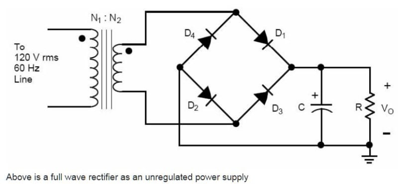
I'd fore shore get the Variac from ebay and I'd use a bridge rectifier (cheap as hell) and a capacitor to make the 125Vdc. A wee bit of DC ripple will make no difference in the DC test.

No reason you can't use the Variac for both tests.

Get one of these.
General-Radio-Company-Variac-Autotransformer-W20MT3-140VAC-20Amp
They're bomb proof. Mine looks like it was tripped on the top stair. Mine also has an ammeter and a volt meter on it which are nice but not necessarily needed since you can add an exterior one.

Rectumfryer

Crapacitor

Wire things well and as a matter of course put something between you and the rectifier and you and the capacitor.

Always turn the variac on at ZERO Volts and turn it up over 5 seconds.

Recognize the capacitor will store a lethal voltage indefinitely after power is removed so mount a Power Resistor across the capacitor. Note it will get pretty warm. This resistor will bring down the cap voltage, on power OFF, to a safe level in about 9 seconds while dumping 22.5 Watts steady-state. There are much sexier ways to handle this safety aspect but none warrant the time or money on this test.

You hook it all up exactly like this. The only difference is the transformer is an autotransformer that's variable. (The Variac)

Unreg_Supply_ojscgb.jpg


Keep in mind that typical Digital Multi Meters will choke on 10A continuously through the crappy test leads. You may need to ebay a real DC ammeter with real screw terminals for the 125Vdc test.

Of course cut out the rectifier and cap for your pot tests.

Wear safety glasses.
Do not do this while talking to anyone.
It's a good idea to have someone "around". (For CPR)

And of course follow the standard rule that you literally - Keep One Hand In Your Pocket.


Keith Cress
kcress -
 
Status
Not open for further replies.

Part and Inventory Search

Sponsor