Continue to Site

Eng-Tips is the largest engineering community on the Internet

Intelligent Work Forums for Engineering Professionals

  • Congratulations waross on being selected by the Eng-Tips community for having the most helpful posts in the forums last week. Way to Go!

Help with Positional Toleranceing for Symmetry 3

Status
Not open for further replies.

AXNRXN

Mechanical
Jan 20, 2009
34
Hey All,

I have a formed sheet metal part similar to that shown. Dataum A is the flat back surface, Datum B is defined by a hole perpendicular to A. Datum C is defined as the center plane of a slot. I want the ears of the sheet metal part to by symmetric to a center plane running through the center or the part. I know that you don't use Symmetry, so I want to call it out with Position tolerance. What are you thoughts of creating a Datum D which is the center plane bewteen the hole and the slot? This is off of a basic dimension which is kinda weird to me. Or, any other way to set this up so that the ears are located by a Position tolerance relative to a center plane?
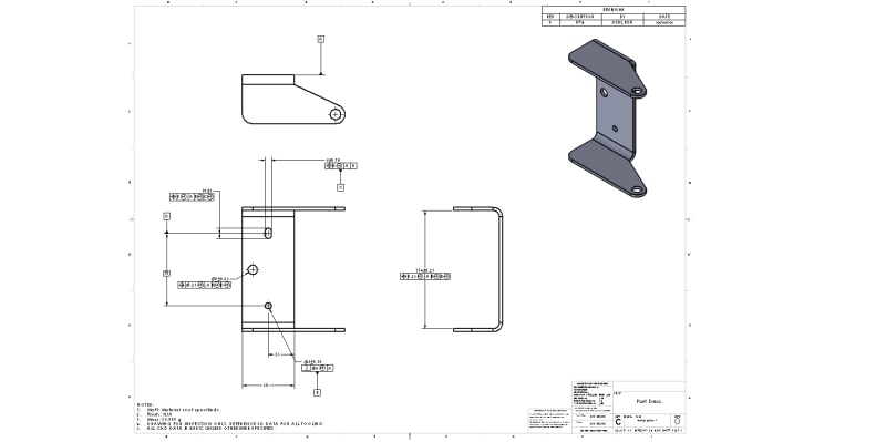
temp_part_1_zzs8m0.jpg

Thanks for any help!
 
Replies continue below

Recommended for you

Well, you could just eliminate D and go over a basic 35 from B, it will do the same thing. Use C for tertiary datum.

You can not have MMC on D anyway.

----------------------------------------

The Help for this program was created in Windows Help format, which depends on a feature that isn't included in this version of Windows.
 
@ dgallup,
Do you mean add a Basic dimension from B to the 9mm hole? How does that form a center plane for locating the 114mm space between the ears? Say, the client's original print had a Basic 35mm dim from B to the 9mm hole, plus another 35mm Basic from that hole to the center of the slot (instead of a 70mm Basic as I show on the print). But, nothing indicating a defined center plane.

I suppose I could do a 22mm Basic from Datum B to the inside wall of the ear, and another 22mm Basic form the center of the slot to the other ear, and then delete the 114mm dimension.
 
AXNRXN,

This is a topic that comes up time and again, mostly due to Y14.5's extensive use of theoretical planes/lines in conjunction with discussion of datum features.

It does not matter where your "planes" are, or are created. If |A|B(M)|C(M)| mimics the functional design intent/assembly condition then that is the scheme you should use, and your position tolerance should be related to those datum features appropriately. Attempting to create a theoretical datum plane which is coincident with the centerplane of the feature of interest will add nothing to your drawing/specification.

I suppose I could do a 22mm Basic from Datum B to the inside wall of the ear, and another 22mm Basic form the center of the slot to the other ear, and then delete the 114mm dimension.

No, this would be improper and your size would now be basic instead of directly toleranced. It is currently dimensioned properly - I would recommend to delete the reference to D (this is not a valid datum feature) and utilize |A|B(M)|C(M)| as noted above.
 
AXNRXN,

I generally agree with chez311, but I do think that a 35 mm basic dimension should be added between the axis of datum feature B and the midplane of the 114 mm width. The midplane should be represented by a center line on the drawing.


pylfrm
 
Make sure to add a note to your drawing stating that the drawing is prepared to ASME Y-14.5 (if that is the GD&T standard you are using).
 
@ pylfrm & Chez:

Pylfrm: Okay, that sounds like it would work. Please let me know if I'm understanding this correctly: Just like on the slot, a Position tolerance on two opposing planes always defines a tolerance zone at the midplane of that dimension. So, in my example, I have a tolerance zone of 0.25mm at the midplane of the 114 dimension, but that's not necessarily located at the center line of the part. However, if I were to indicate that center plane by drawing a center line in that view, I could create a Basic dimension (coming from the pin)to that center line. By doing that, I'm saying that the True Center line lies 35mm from the pin, and the tolerance zone from 114mm Position has to encompass that center line. Would I leave the Primary, Secondary, Tertiary datums in the control frame the same? Let me know if I'm off on this.

Chez: What I typed doesn't make any sense after rereading it. If I were to dimension from the pin and slot center to the faces of the ears, I'd have to create a 22mm dimension from the center of the pin, then apply a Perpendicularity tolerance to Datums A and C. I think this would also work, but kinda gets rid of the Symmetry implications that the original drawing had.

Thanks for the help, y'all. Much appreciated.
 
Okay, that sounds like it would work. Please let me know if I'm understanding this correctly: Just like on the slot, a Position tolerance on two opposing planes always defines a tolerance zone at the midplane of that dimension. So, in my example, I have a tolerance zone of 0.25mm at the midplane of the 114 dimension, but that's not necessarily located at the center line of the part. However, if I were to indicate that center plane by drawing a center line in that view, I could create a Basic dimension (coming from the pin)to that center line. By doing that, I'm saying that the True Center line lies 35mm from the pin, and the tolerance zone from 114mm Position has to encompass that center line.

If I may, it seems like there are some misunderstandings that might benefit from reading through the text of the standard. The "two opposing planes" you describe is a Regular Feature of Size. To apply a position tolerance, the centerplane of the 114mm wide Feature of Size (FOS) must be basically located to your datum features in order to be properly constrained to the Datum Reference Frame (DRF). As it stands, your inference that the centerplane of the 114mm feature lies between (35mm away from) each of the centers of the datum features is an assumption. Pylfrm's suggestion makes this explicit.

Also theres the seemingly small, but in reality very important, matter of semantics - the tolerance zone is located to/defined by the datum feature references not from the feature being controlled. The centerplane of the feature must fall within that zone.

What I typed doesn't make any sense after rereading it. If I were to dimension from the pin and slot center to the faces of the ears, I'd have to create a 22mm dimension from the center of the pin, then apply a Perpendicularity tolerance to Datums A and C. I think this would also work, but kinda gets rid of the Symmetry implications that the original drawing had.

I'm not really sure where you're going with this, and it still would not properly locate the tolerance zone/feature. See my above response.

Additionally, I noticed you reference the width of the slot datum feature C position to |A|B| and the length positioned to |A|B(M)|C(M)|. I don't know if you meant to reference B at both RFS and MMB. Also I would suggest referencing both the length and width at |A|B(M)| even though only the width is utilized as datum feature C as this will hold the entire slot together to simultaneous requirements.
 
Thanks chez311. Yes, what you wrote in your last post is how I understand it. I will also set up the datum references as you suggest. It makes sense to me calling it out that way.

I've uploaded another PDF with what I believe you guys agree is the correct method. Let me know if you think I'm missing something.
temp_part_1b_s00nir.jpg
 
AXNRXN,

Your latest post does not link to a PDF, and the image isn't really readable. If I imagine some more pixels, it looks like it's probably valid. Whether it's correct for the application is a different question, and we don't have enough information about the part's functionality to answer that.

For what it's worth, the actual meaning of the 0.25(M) position tolerance applied to the 114 +/- 0.25 width is that the feature must not violate a boundary of width 113.50 (=114-0.25-0.25) located at true position. The idea that the feature midplane must fall within a tolerance zone of width 0.25 (plus bonus) is an approximation that's included in the standard, but it's not the final word.


pylfrm
 
AXNRXN,
With the updates, your new drawing looks valid as pylfrm noted.

Pylfrm,
I considered including a note about that in my initial response, but I removed it because I figured the resolved geometry interpretation would be easier to envision and/or fit better into most people's paradigm (positioning a center point/plane/axis within a tolerance zone). Of course as you alluded to for MMC the surface interpretation is the final word.
 
Actually I may have spoke too soon. The 9mm hole is missing basic location from your datum features. Also not entirely sure exactly what you're trying to accomplish with the 25mm distance/50mm width - if it is truly not critical I guess you could leave it as shown and leave the tolerancing of these dimensions to a general print tolerance, just know they may vary wildly in measurement (no support for directly toleranced location in Y14.5) or you could utilize a similar scheme to the 114mm feature (remove 25mm dim, add centerline/size/position tolerance) or something else such as profile (requires all basic dimensions).
 
A centerline should be added between datum features B and C or "2X" added to the 25 horizontal dimension (if the slot and the hole are on a common centerline). Also, as chez311 alluded, a horizontal dimension locating the Ø9 hole relative to B, C is needed.

"Know the rules well, so you can break them effectively."
-Dalai Lama XIV
 
Chez / ewh,

Yes, correct. I need a basic dimension coming from the plane formed by Datums B & C out to the 9mm hole. The 25mm and 50mm untoleranced dimensions will get a simple tolerance. The original print didn't have anything specific going on with those two dimensions, so I think I can keep them that way.

ewh, this might be a bit nit picky, but would I need the (2X) call out on he 25mm dimension? Say, the way I think about it is that Datum C calls out a center plane at the center of the width of the slot. Since that slot calls out Datum B, it is assumed that C and B lie in the same plane (unless otherwise noted). So, the 25mm would be dimensioned *from* Datum Plane C to the edge of the part. If instead the front edge of the part was a datum and I was dimensioning the hole and slot from there, then I would need the (2X) call out.

Thanks for all the comments. Really helps!
 
 https://files.engineering.com/getfile.aspx?folder=cdb1968a-7dd3-4425-a473-f5fd9a802145&file=temp_part_1c.PDF
AXNRXN,

As currently shown, the 25 +/- 0.25 dimension has nothing to do with datums. It just controls the relationship between the flat surface and the hole. Using a toleranced dimension in this way is generally not recommended though.

If you want to control the relationship between the flat surface and a plane derived from the datum features, you should probably change the dimension from toleranced to basic. You could then apply a tolerance such as [box]profile[/box][box]0.5[/box][box]A[/box][box]B(M)[/box][box]C(M)[/box] to the flat surface.

Due to note 5, most of the discussion about basic dimensions is probably unnecessary. I failed to consider that when when I wrote my earlier replies, and it appears I'm not the only one.


pylfrm
 
Thanks, pylfrm.

I guess you are right. I could control that flat edge of the part better. I suppose that the edge could rotate around that hole to the angular tolerance shown in the block, as long as the 25mm tolerance holds. I believe that particular edge would be an implied 90-degress to the center line? I don't want to add too much inspection on the part either if not necessary. I could do a parallelism tolerance as well? It kinda comes down to what is easier to inspect between Profile and Parallel. It seems like Profile is used quite often and maybe it's due to easier inspection. It seems more straight-forward to run a gauge along that edge and inspect a Profile tolerance against a Basic dimension, rather than try to inspect a Parallel tolerance based off of Datum C.
 
I suppose that the edge could rotate around that hole to the angular tolerance shown in the block, as long as the 25mm tolerance holds.

There are all sorts of variation which is possible when direct (+/-) tolerancing is utilized in situations which Y14.5 does not support.

I could do a parallelism tolerance as well? It kinda comes down to what is easier to inspect between Profile and Parallel.

A parallelism tolerance still requires the feature be located somehow - either with position (directly toleranced FOS + position tolerance) or profile (basic dimensions). If your concern is ease of inspection I would think a single MMC position tolerance with no additional parallelism requirement would be the most simple solution.
 
Hi Chez,

I'm still a bit confused on how Position would be used for tolerancing that edge. Say, if i used position across that 50mm face, it just so happens that the center plane would align with Datum C (within a specified Positional tolerance)? It would work just like the 114mm dimension on the print. I've uploaded a PDF of this scheme. However, what if Datum C did not lie in the center of the 50mm face? Say, what if the Pin and Slot were only 10mm from that front edge? Would I then have to create a Basic dimension to where the center plane of the 50mm face is supposed to be? This would be similar to how I define the center line of the 114mm ears with the 35mm Basic dimension.

Sorry for the hypothetical. It help in the greater understanding of Position.
 
 https://files.engineering.com/getfile.aspx?folder=3ad15fb0-aada-4825-8d8b-96b866d6d32a&file=temp_part_1d.PDF
Status
Not open for further replies.

Part and Inventory Search

Sponsor