Continue to Site

Eng-Tips is the largest engineering community on the Internet

Intelligent Work Forums for Engineering Professionals

  • Congratulations waross on being selected by the Eng-Tips community for having the most helpful posts in the forums last week. Way to Go!

Help with Positional Toleranceing for Symmetry 3

Status
Not open for further replies.

AXNRXN

Mechanical
Jan 20, 2009
34
Hey All,

I have a formed sheet metal part similar to that shown. Dataum A is the flat back surface, Datum B is defined by a hole perpendicular to A. Datum C is defined as the center plane of a slot. I want the ears of the sheet metal part to by symmetric to a center plane running through the center or the part. I know that you don't use Symmetry, so I want to call it out with Position tolerance. What are you thoughts of creating a Datum D which is the center plane bewteen the hole and the slot? This is off of a basic dimension which is kinda weird to me. Or, any other way to set this up so that the ears are located by a Position tolerance relative to a center plane?
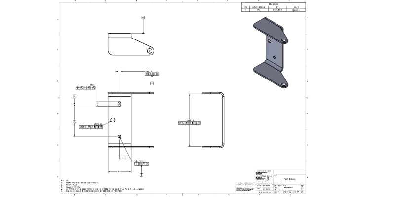
temp_part_1_zzs8m0.jpg

Thanks for any help!
 
Replies continue below

Recommended for you

Say, if i used position across that 50mm face, it just so happens that the center plane would align with Datum C (within a specified Positional tolerance)? It would work just like the 114mm dimension on the print.

Yes, this makes no difference. The center plane being coincident with the centers of the datum features implies a 0 basic dimension.

Say, what if the Pin and Slot were only 10mm from that front edge? Would I then have to create a Basic dimension to where the center plane of the 50mm face is supposed to be?

Yes. The centerline/plane must be basically located from your datum reference frame - since this would no longer be implicit 0 basic as your hypothetical 10mm shift is no longer coincident and requires explicit dimensioning. Both schemes you have shown should work (might do with a centerline shown like you did with the 114mm width) - though if you are looking for ease of inspection position at MMC instead of RFS might be recommended, in addition to the MMB datum references shown.
 
Unlike the 114 mm width, the 50 mm width has a lot of non-opposed elements, so from this perspective treating it as a feature of size and using position tolerance might not be the best choice.

Since the drawing is per Y14.5-2009 and in millimeters (as specified in the title block), some leading zeros are missing in feature control frames and some trailing zeros are not needed in +/-0.10 tolerance specifications. Also, the slot C is missing radius dimension '2X R' (see fig. 7-34 in Y14.5-2009).
 
The tolerance as shown applied to the 50mm width would of course only apply to that portion which contains opposed elements. I sort of had tunnel vision and was ignoring the rest of the feature and focusing on the "ease of inspection" part. Tim_member is correct though, profile may be a better choice in this case.
 
I agree with you guys. I like a Profile on that feature. The Position tolerance kinda makes it confusing to me, but it is a simple way to tolerance the drawing. I wanted to pose the question as it helped me understand how a Position tolerance would work in the centered & offset cases. This drawing is just a temp quickie for discussions sake. I'll be sure to mind the leading zeros and radii and such. Just got in my new Y14.5-2018 standard ($230!!!), so I'll be referencing that.
 
Y14.5-2018 gives a recipe for dealing with size specification for features of size that don't contain opposed points. See para. 5.8.1(e).
 
Tim,

Fo rthe non-opposed elements, I think you are referring to the vertical edge of the bent ears? Say, I get that the Position Tolerance on the 50mm dimension covers the flat portion with the holes/ slots in it. But, as that edge bends and travels up the ear, the Position might not apply. The 5.8.1e kinda applies here if that edge were considered just a localized area of non-opposed elements. But, best I think to put a Profile tolerance on that vertical edge in the view that shows the shape of the ear. I'm starting to see why people tend to use a bunch of Profile tolerances. It seems to cover a lot of situations.
 
Yes, that's what I am referring to and yes, I think that profile of a surface applied to both faces of the 50 mm width is the best choice. As soon as you start tolerancing other features of this part, that haven't been discussed here, you will notice even more how powerful profile tolerance is/can be.
 
tim_member,

OP's initial drawing called out Y14.5-2009, since the latest post (10 Jul 19 16:30) stated 2018 will be utilized then you are correct 5.8.1(e) does provide a method to control the limits of size of portions of a RFOS which lack directly opposed points. I had initially considered this, however it would be utilizing the UAME of a feature which has a very high length to width ratio as it is (which can make establishment/measurement of a UAME dicey -hence the beauty of MMC) to control size of a portion of the feature lacking directly opposed points which extends past and is ~3x as long as the portion which has directly opposed points. Though I guess probably "legal" - excepting the fact that the standard utilizes the nonspecific term "localized area(s)" and that there is no version of the math standard to support this new interpretation* this just seems like a bad idea.

I'd be interested to hear others opinions on this as well. This is mostly theoretical anyway - I think we agree that profile is probably the better choice in this application.

*the new planned release of Y14.5.1 will only be compliant to Y14.5-2009, though I guess it wouldn't take much effort to extrapolate the swept spheres definition of size from being measured only to the feature instead between the feature and the UAME boundary
 
I have been in and out of this thread. I noticed in chez_311s' last post, a mention of irregular FOS at RFS was discussed. I am "weak" in the RFS area. I haven't thoroughly read through Y14.5-2018 to see what if offers in the way of RFS topic, but I did go chasing this "RFS" topic with datums and found something that doesn't line-up. So...Referring to 7.17(b), page 80 in 2018: the text refers to figure 11-29 but I can not see how this figure relates to the "RFS" topic for datums in 7.117(b). Does anyone agree this might be a bad reference?

Certified Sr. GD&T Professional
 
ASME Y14.5-2018 said:
(b) In other applications (such as an irregular shaped
feature) where a boundary has been defined using profile
tolerancing, a center point, an axis, or a center plane may
not be readily definable. See para. 3.35.1(b) and Figure 11-
29. MMB and LMB principles may be applied to this type of
irregular feature of size. When RMB is applicable, the
fitting routine may be the same as for a regular
feature of size, or a specific fitting routine may be
defined, or datum targets may be used.
NOTE: Datum feature reference RMB may become very complex
or not be feasible for some irregular features of size.

Well first this section deals not with RFS but with MMB/LMB/RMB (maybe pedantic I know but pointing it out). I would say fig 11-29 is an example of a feature "where a boundary has been defined using profile tolerancing, a center point, an axis, or a center plane may not be readily definable" and therefore if it were referenced MMB or LMB then as it says MMB/LMB principles would apply or if it were referenced RMB a fitting routine or datum targets could be used.

Side note - where did you see I discussed an IFOS at RFS/RMB?
 
chez_311

Thanks for your comments. 7.17 deals with datums and figure 11-29 does not have a profile-controlled feature as a datum -that's why I ask the question.

I mentally tie RFS, RMB and Rule #1 concepts under one "roof". Sorry for the confusion.

Certified Sr. GD&T Professional
 
mkcski,

I think the point was probably to show the type of feature which they are referencing (IFOS with center point/axis/plane not readily definable) as well as what the boundary for MMB for such a feature might look like. I agree it might be a better connection had the feature of interest be shown referenced as a datum feature and possibly at several different boundary conditions.
 
Chez_311

I agree. I attended a Y14.5 Committee meeting a few years ago. One discussion was how to reduce the number of figures to lower the printing costs - less pages. They were looking a revising figures so one figure could relate to many topics. I guess this one wasn't scrutinized enough.

I do like the format of 2018 where the figures are not interspersed with the text.

Certified Sr. GD&T Professional
 
If they were trying to reduce page count, they failed miserably... the length of the standard has ballooned because of the larger figures (I don't remember in 2009 having much difficulty with readability - many in 2018 take up most/all of a single page) and the addition of MBD examples - which I might be biased since I don't use MBD but I wish they had been left off for the most part and reserved for the MBD standard Y14.41. Also I'm divided if I like the new format or not - its nice in some cases to have all the figures together but its a pain to flip back and forth when a figure is coupled with a particular portion of the text - though as you say they are being referenced/consolidated for multiple topics so that would be an issue regardless I guess..

I don't mean to sound like a pessimist, what I've read in the standard so far there are several places where additional useful examples have been added and the text has become more specific and cleaned up some ambiguity. Obviously nothing is perfect though.
 
To all (pylfrm I'm kinda looking your way, I respect your knowledge on these topics immensely) - I'm interested if anyone has any input on my post from (11 Jul 19 13:00) about the new interpretation of size deviations on a regular FOS with interruptions/non directly opposed sections.
 
CHEZ311:

CHEZ311 said:
[/ however it would be utilizing the UAME of a feature which has a very high length to width ratio as it is (which can make establishment/measurement of a UAME dicey -hence the beauty of MMC) to control size of a portion of the feature lacking directly opposed points which extends past and is ~3x as long as the portion which has directly opposed points]

Let me add my two cents: reading 5.8.1(e) is says "distance at any cross section". You indicate a concern about length to with ratio. Since the UAME only applies at each cross section, the UAME does not apply to the entire surface, and the ratio is a non-issue.


Certified Sr. GD&T Professional
 
mkcski,

I'm not sure what you mean by "Since the UAME only applies at each cross section, the UAME does not apply to the entire surface" - I don't know exactly what you mean by this or where its supported in the standard. Contraction/expansion of an envelope around/inside an external/internal feature to is minimum/maximum size (respectively) defines the UAME - this certainly involves the entire surface.

See the thread on ( for a discussion on some of the issues that may arise with high length to width (or rather, width/length) ratios. About halfway through is where the discussion on this topic starts. For a more exaggerated case but to illustrate what I'm talking about imagine trying to derive a UAME from the short edges of a large, thin sheet metal part - a dubious proposition at best. HOWEVER that being said, after doing some layouts/sketches in CAD it looks like the lengthy extension of the one unopposed side actually stabilizes the part and envelope as opposed to the shapes shown in the referenced thread - even with maximum form deviation ie: convex error. This might change if the allowable size/form error were significantly greater but on the order shown (+/-0.25) I was unable to find a configuration that was notably unstable (ie: allowed unlimited contraction/lack of local minimum). Perhaps someone else can though.

As far as I can tell the only issue I can see is lining this interpretation up with the definition of size in Y14.5.1 however I don't know that it would take very much extrapolation to do so. Perhaps it would be not much unlike size verification of the boundary of an irregular FOS such as those shown in Fig 7-42 in Y14.5-2018?
 
CHEZ311:

Sorry, my response was not clear as it could have been. You asked about the size impact. I was trying to rephrase 5.8.1 (e) as it relates to size. I guess I "missed".

I reread you original "13.00" post and misunderstood what you were asking. I agree the ratio has a impact. I have no suggestions. Like many other requirements in the standard - they have to be subtly "customized" (applied and interpreted) differently from one industry to another. Sheet metal industry vs one with more "volumetric" parts.

Certified Sr. GD&T Professional
 
chez311,

First a disclaimer: I have the 24 November 2015 draft and 08 November 2017 list of changes, but not the actual ASME Y14.5-2018 standard. The paragraph numbering appears to have changed, but I will assume there are no technical differences relevant to this discussion.

It's hard to imagine a good functional reason to use a toleranced size dimension for the 50 mm width in OP's example. I haven't tried to analyze all possible results of the various size tolerance definitions, but I will offer an example that highlights a difference. In 2D, imagine the larger surface is the line segment connecting (0, 0) to (0, -37) and the smaller surface is the line segment connecting (50.2, 0) to (49.8, -9). The UAME size is approximately 50.1505, determined by contact with the feature at (0, 0), (50.2, 0), and (49.8, -9). The distance from the far side of the UAME to (0, -37) is approximately 48.5077, which presumably means the feature is out of tolerance per the Y14.5-2018 definition. Per the Y14.5.1M-1994 definition, the same geometry meets the tolerance with a margin of at least 0.05 on both limits. Which answer do you like better?

The size tolerance definitions in Y14.5-2009 and -2018 both use the term "actual local size". Unfortunately the definition of "actual local size" leaves a lot to be desired. Y14.5-2009 does not appear to address unopposed portions of features, and fails to mention that Y14.5.1 covers the subject. For some reason a new incompatible definition was invented for Y14.5-2018. It would be interesting to know the rationale behind these decisions, but I don't imagine we're likely to find that out.

It seems potentially problematic for determination of size tolerance compliance to require determination of the UAME. In some cases the measurement uncertainty of UAME size would be small, but the uncertainty of UAME location would be large. That could lead to large uncertainty of actual local sizes that are measured from the UAME. That's not necessarily a big problem, but it is an added complication. Perhaps I haven't looked hard enough, but I'm not sure I see a need for the change.


pylfrm
 
ASME Y14.5-2018 said:
(e) Where a portion of a regular feature of size has a
localized area(s) that do not contain opposed points, the
actual value of an individual distance at any cross section
between the unrelated AME to a point on the surface may
not violate the LMC limit. See Figure 5-9.

pylfrm,

See above for the text from the Y14.5-2018 standard, I'm sure its pretty similar to the drafts which you have but just for reference I have included it. I agree that in OP's case a toleranced size dimension is not a very good solution, my question is mostly theoretical as I have been wondering about some of the implications of the new 2018 approach of dealing with unopposed elements since I first read it.

First off, could you help guide me to where Y14.5.1-1994 provides a solution to determine size for unopposed portions of a FOS? I was not aware that the math standard had a method of dealing with this - perhaps its not directly addressed (skimming it a few times I don't see any direct references to this) but comes from an interpretation of the swept spheres definition of size in 2.3 ? If I read between the lines a bit, does it maybe have to do with rule #1 and utilizing a boundary of perfect form at MMC to provide a basis to limit size variation of unopposed sections? I think I see what you're getting at, but your help in understanding this would be immensely educational!

The size tolerance definitions in Y14.5-2009 and -2018 both use the term "actual local size". Unfortunately the definition of "actual local size" leaves a lot to be desired.

I fully agree - honestly I've mostly assumed any references to "actual local size" is superseded by the swept spheres interpretation of size provided by Y14.5.1 - indeed the new draft for the Y14.5.1 update provides a section detailing two other methods to determine "actual local size" (2-point measurements and measurement at cross-sections/circular elements) which are presented as approximations to determine size conformance but the swept spheres takes precedence.

It seems potentially problematic for determination of size tolerance compliance to require determination of the UAME. In some cases the measurement uncertainty of UAME size would be small, but the uncertainty of UAME location would be large. That could lead to large uncertainty of actual local sizes that are measured from the UAME.

Could you clarify a little by what you mean by this? Are you considering cases where there is instability or multiple solutions (ie: rocking) ? Do you believe the interpretation per Y14.5.1-1994 is more robust or "better" or just different? It seems to me that the addition of multiple constraints on the size of a single feature (ie: must satisfy swept spheres independent of the UAME for sections with opposed points, must satisfy swept spheres dependent on the UAME for sections with unopposed points) could be problematic, if a current interpretation per the math standard is available. It leads one to wonder if those on the committee were unaware of this interpretation (hopefully not) or as you say had a legitimate rationale to present a conflicting definition - I guess thats left to the imagination.
 
Status
Not open for further replies.

Part and Inventory Search

Sponsor