Eng-Tips is the largest engineering community on the Internet

Intelligent Work Forums for Engineering Professionals

Help with recirculating pump above tank level 1

tonbaldin

Chemical
Aug 30, 2024
5
0
0
BR
Captura_de_tela_2024-08-30_172917_jl8wdb.png

Hi all!

I need help with commissioning this pump. The design engineer is not around anymore and now I'm responsible.
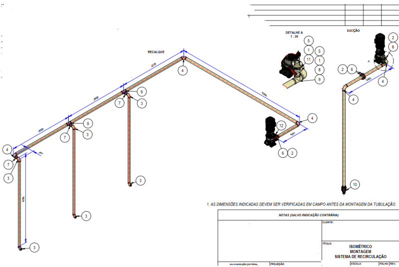
The idea is to use the centrifugal pump to recirculate and agitate the liquid in the tank.
The piping has an internal diameter of 90 mm. I've already made some calculations for the headloss and maximum suction lift accordint to manufacturer's operating manual and concluded that I had to reduce the pump speed, because the headloss was too high. Even with 1750 rpm the pump can't lift the liquid and recirculate.
I'm considering to increase the pipe's ID to 130 mm so maybe I can operate the pump at full speed.

Any thoughts or ideas that I should try before replacing the piping?
 
Replies continue below

Recommended for you

What are all those items?
What is the actual suction lift distance?
The diagram can't be read.
Which is the suction line?

Remember we can't see what you can so you need to explain s bit more.

Centrifugal pumps can "lift" water, but only when full. They don't self prime as a rule.

How is the system designed to have full pipes

Remember - More details = better answers
Also: If you get a response it's polite to respond to it.
 
Thanks for pointing out. Didn't see that the image was illegible.
At the suction side I have:
1 foot valve
2 elbows
1 straight tee (where I have a valve for priming thr system)
6m of linear pipe

At the discharge side:
2 elbows and 9 m of linear pipe before three branches (two tees and an elbow)
Each branch has a reducer and an elbow after 3m of linear pipe
The distance between each branch is 3m
The reduced pipe ID is 75 mm.

The maximum height difference between the liquid level and the pump's CL is 4m.
 
download.aspx


"I had to reduce the pump speed, because the headloss was too high. Even with 1750 rpm the pump can't lift the liquid and recirculate."

If you reduce speed to 1/2 max rpm, your head drops to 25% of the head at max rpm and your flow drops to half.
So you can see that it is a losing proposition.

3 bars is 30m of head or some 100 ft.
At 116 m3/h, that requires 10kW hydraulic power
If 0.77 is efficiency, then you need 13kW brake kW

You start at 4m in the hole, so add that to the pump power and head required.

Looks like you may not have enough, or maybe just barely enough power to lift your flow 34m
Increase your pipe diameter and see how much power you need.

Will the pump draw the 4m on suction side?


--Einstein gave the same test to students every year. When asked why he would do something like that, "Because the answers had changed."
 
I'm a bit lost here as to what the problem is.

That looks like a big flowrate (130m3/hr) for a 90mm ID pipe.

You need to prime the system to get it working.

What happens [ul]
[li][/li]
[/ul]when you turn it on?

Remember - More details = better answers
Also: If you get a response it's polite to respond to it.
 
He could be more confused than us.


--Einstein gave the same test to students every year. When asked why he would do something like that, "Because the answers had changed."
 
Sorry for the absence, guys.

I also believe that it is a small pipe.
I prime the system and start the pump with the VFD at 50% and it works.
But if the tank's level gets lower, the system stops.

The main concern here is that the pump doesn't deliver the design flowrate. That's why I'm considering change the suction pipe ID.

One thing I should clarify is that the operation point shown in the pump curve is not "real", it was only used for pricing.
The discharge of the pump is in the same tank as the suction, then when I use Bernoulli's equation for calculating the operation point, only the friction loss remains, resulting in an operation point with a good flowrate. However, at this flowrate, the pump doesn't lift the water.

I don't know if I'm doing something wrong in the calculations, but with those I concluded that at 50% the pump would work.
 
Ok,

That's more info.

What you need to do is measure flow.

I think what is happening is that as your tank drops in level and on the basis that it's the same tank, I think your flow is increasing to the point where your pretty high NPSHR / cavitation is cutting in.

Even at 100m3/hr it says about 0.4 bar. Cavitation is higher than that so maybe 0.5 bar. Your lift at 4m max is getting pretty close.

But that pump looks very sensitive to flow on NPSH once you go above ~100m3/hr

I would run it a bit faster and stick a control valve on the outlet at 100m3/hr

Remember - More details = better answers
Also: If you get a response it's polite to respond to it.
 
Hi tonbaldin,
Could be a good start to review the pumping design calculation on too positively assumed values or missed items, as liquid accelleration & resistance at suction line inlet, resistance of the foot valve and vapor pressure.
Another point could be air bubbles or even an air layer in the horizontal part of suction line due to not being fully primed or due cavities in the pipe at starting up the pump. That would increase the suction line pressure drop and have a negative effect on the NPSH.
 
2 and 6 looks like a valve and flanges

3 and 4 are elbows but a different size.

Remember - More details = better answers
Also: If you get a response it's polite to respond to it.
 
2 and 6 look like flow orrifice, what is the worst idea for a self-driven vacuum custion line

note that item 10 (check valve) does not work as it is intended as the pump case is self drained through downstrream discharge line
 
I don't think this system will draain unless there is an air release valve.

The start and end water level is the same so once the system is fully primed should just sit there unless there is an air inlet somewhere.

So you don't need the foot valve which could be adding extra losses.

2 and 6 could be a flow measurement device alright, which should be on the discharge side to again reduce inlet losses.

I would remove the foot valve, get a flow measurement device on the discharge side and keep it below 100m3 /hr

Remember - More details = better answers
Also: If you get a response it's polite to respond to it.
 
unless there is an air inlet somewhere.
this pump is a rotary machine, it is only matter of time 'unless' and having experience with operating in a field such design for >5 years I should say this 'unless' is easily might be surprisingly brief

My core idea is that this leak is so small that it is unable to find. All will be ok until all is ok. Immediately a something negligibly small goes wrong such design brings a big bunch of problems to fight against.

I would remove the foot valve
I do not recommend delete item 10 as it helps to fill pump suction for priming. Otherwise liquid amount to be spent for priming is much higher and there is a risk overfilling a tank

3 and 4 are elbows but a different size.
In such case why the reducer 7 at the very left of drawing is not connected to the left tee? Why to elbow 4 at the very left of drawing?
 
shvet.

It's all the same tank so there is no filling, but depends on how they prime. filling the system with a second water supply or vacuum. We don't know.

reducer 7 is connected to larger elbow 4.

I can only presume they never wanted to extend the system so instead of a tee inserted an elbow. Pretty common on the end of header if not a great way to design for no future connection potential.

Foot valves tend to leak as well so often you wonder if they are worth the bother.

Remember - More details = better answers
Also: If you get a response it's polite to respond to it.
 
Thanks for all the answers.

What are items 2 and 6 on drawings?
2 and 6 are the flange fittings, because the welding neck and the flange are sold separately.

In such case why the reducer 7 at the very left of drawing is not connected to the left tee? Why to elbow 4 at the very left of drawing?
Aesthetic purposes. Decision comes from boss.

It's all the same tank so there is no filling, but depends on how they prime. filling the system with a second water supply or vacuum. We don't know.
Second water source.

We've decided to increase the suction pipe ID to 130 mm. I believe this will solve my low flowrate issue.

this pump is a rotary machine, it is only matter of time 'unless' and having experience with operating in a field such design for >5 years I should say this 'unless' is easily might be surprisingly brief
My core idea is that this leak is so small that it is unable to find. All will be ok until all is ok. Immediately a something negligibly small goes wrong such design brings a big bunch of problems to fight against.

Should I install an air release valve at the discharge line?
 
Measured flowrate?

Go too fast and you'll exceed NPSH.

Remember - More details = better answers
Also: If you get a response it's polite to respond to it.
 
Agreed, suction line velocity is too high, 130mm will help reduce suction losses.
Also check for vortexes around the suction line at high flow - it may be pulling in air. There is also some requirement for a min submergence to avoid pulling in air. Vortex breaker baffles installed in this suction source tank ?
 
@tonbaldin
The more info you disclosed the more this system seems like there is no engineering behind that. At this moment you have striken the combo:
(1) gas pocket at suction
(2) significant flow restriction at suction (flow orifice)
(3) no block valve at discharge (filling is empede)
(4) non-uniform flow distribution between nozzles
(5) circulation rate is uncontrolled
(6) intake has no bell for vortex shedding (see ANSI/HI 9.8)
(7) check valve is prone to clogging by floating debris
(8) suction DN is undersized

I suppose there are more items to extend this combo you are hiding from us.

You should comprehend 3 critical points:
(1) this circulation loop works under vacuum
(2) suction pipe is self-driven
(3) there is no point the gas to escape
A gas trapped in loop accumulates and expands until gets into impeller and making it runs idle and this way breaking the syphon.
A gas source is not important as there many of those: sucked in through a small leak, non-displaced by water during priming, got to intake by vortex, degassed by pressure drop, or whatever I might not mentioned.

Challenges in compensating these is the reason why [semi-]submersible pumps are more popular than priming ones are.
 
Back
Top