Eng-Tips is the largest engineering community on the Internet

Intelligent Work Forums for Engineering Professionals

HELP WITH SCHEMATIC 1

Status
Not open for further replies.

roboshlob

Electrical
Dec 4, 2020
3
0
0
US
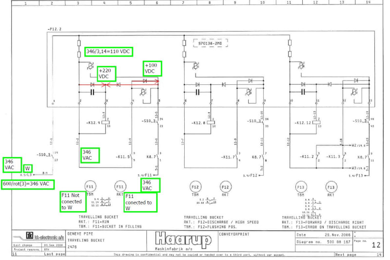
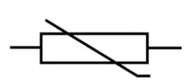
I am working on installing this new system for a company and there is some confusion on what this component is. The original manufacturer is out of business, and has been for a while. I cannot find any information on the part or anything. Its like a ghost. So, according to this print I am to wire 3 phase, 480vac to UVW. Now, they are sending a and b phase to power the primary side of a control transformer (pg8). C phase (L3 in the print) they send to terminal 1 on the unit in question (pg 12). F11, F12 and F13 are inputs associated with each sub-circuit of the device and close the associated relays corresponding to their respective outputs (k12.4, k12.8 and k12.12). These relays tied to these outputs are 110 VDC coils, so I am assuming that this component (page 12) is some sort of rectifier that takes 277vac signals and rectifies them for use within this system. Their people (who have never worked on this machine) are telling me I am to put 24vds signals to f11, f12 and f13. I don't see how that is possible with 277vdc being common between all 3 circuits inside of the component. I'm not quite sure what the blank boxes are at the top of each circuit, within the component (pg 12), or the box with the line through it diagonally (pg 12). when I TEMPORARILY jump 277v to F11, f12 and f13 those relays energize. Have any of you guys seen this circuit before, and what are the two symbols (besides the diodes and N.O. contacts in each subsystem in the component?
 
 https://files.engineering.com/getfile.aspx?folder=f6e83e61-1d61-4b24-81a4-188b83454959&file=5-8-12.pdf
Replies continue below

Recommended for you

Typically a box with the line through it is a MOV, or metal oxide varistor. But I've never seen the short interruption in the line connecting to the MOV. Boxes with lines to them are usually solenoids, but sometimes represent the coil of a relay. It all looks a little odd to me - almost like fluid logic symbols mixed with electrical symbols.
 
Too many pages missing for me.
This may help:
On page 5
F11/12.6 Goes to F11, page 12. column 6.
On page 12:
5.4/F11, Comes from F11, page 5, column 4.
K may be Kontactor or Koil.

Bill
--------------------
"Why not the best?"
Jimmy Carter
 
Those are indeed MOVs on page 12. The gap is some sort of document error. There are random lines missing elsewhere in the document.

The two 'boxes' at the top of those pg12 lines are likely dropping resistors. They may vary with supply voltage.

The K12.4, 12.8, and 12.12 are the coils for the contactors. K is common for that designation. Those coils are being driven by rectified AC with the unlabeled capacitors providing valley filling to keep the coils from chattering.

It would certainly be more useful having the ENTIRE schematic.

Keith Cress
kcress -
 
here is the entire print....I only included those three pages since that's the only part of the system that I'm having questions on....just that component on page 12. It clearly derives its common (input 1) from a 277 v source shown on page 5. Page 8 shows where 2 legs feed a 480 to 230vac transformer and page 12 is where the 3rd leg breaks off and feeds said component. All the other pages pertain to other parts of the system I'm not concerned with. I just want to make sure that f11, f12 and f13 are in fact, 277vac inputs.
 
 https://files.engineering.com/getfile.aspx?folder=ef9a86da-fa9a-4eed-a0f0-bf9c9e73f71c&file=2_-_Electrical_diagram.pdf
As Keith suspected, the two plain boxes at the beginning of each circuit in P12.2 (whatever that is) are IEC symbols for resistors, so likely dropping resistors to bring that 277V down to probably around 78VAC so that when rectified, it becomes 110VDC.


" We are all here on earth to help others; what on earth the others are here for I don't know." -- W. H. Auden
 
Exempel_qgpvvc.jpg

Do not know if this helps ??
Or if I'm out on a very thin branch :-/ here.. lot of speculation due to non-existent mechanical drawings ;-)

The drive can not be run unless the inductive sensor -B11.5 is unaffected and it must be a dark on signal, it will be high if it is unaffected and 0 when it is.
When the buket arrives for loading the induktive sensorer signal goes zero and -K11.5 falls and the inverter stops and can not be run. When the bucket is full, the sensor becomes unaffected and the signal goes high and -K11.5 pulls. (Probably some tipping cradle and with the help of Newton.)
Then F11 is also connected to phase W in the cunducor trolly so that -K12.4 can pull and the frequency converter can start again.

As I tried to describe, I think that it is the voltage difference across the relay that is 110 VDC on the upper side A1, both the positive and negative alternating voltage is rectified so that it becomes 346 / 3.14 * 2 = 220 VDC while on the lower side A2 it is just positive AC voltage it, 346 / 3.14 = 110 VDC so the potential difference across the relay becomes + 110 VDC when -K11.5 is drawn and F11 is connected to L3 = W.
3 phase 600VAC /1,73 = 346 VAC (1 phase)

As someone pointed out it is a varistor for surge protection if it is connected its probably for cutting of any spikes from the cunductor trolly brushes.
Varistor_ozoapl.jpg


If I did not get everything completely wrong now ...
I would say that it will be difficult to rebuild this regardless of "the black box".
May I ask why they want this relays changed and this rebuilt?

Best Regards A

“Logic will get you from A to Z; imagination will get you everywhere.“
Albert Einstein
 
-P12.2 is probably a printed circuit.
Not stated - I suspect it needs board level repair due to some sort of damage to a component or the board.

The discussion above looks like it has enough information about what the board does to help with troubleshooting. For repairing the board, I think getting the component data off of the actual board is often possible. If you do not have your hands on the board, perhaps an electrician can get you pictures?

As there are three circuits that look like duplicates of each other, even if part of the board is damaged to the point it can not be examined, you can probably get enough component data to make reverse engineering the bill of materials simpler.

None of these components should be difficult to cross reference to currently available components. If the existing board is unusable, try using a prototype board for assembly.

Fred
 
Status
Not open for further replies.
Back
Top