roboshlob
Electrical
- Dec 4, 2020
- 3
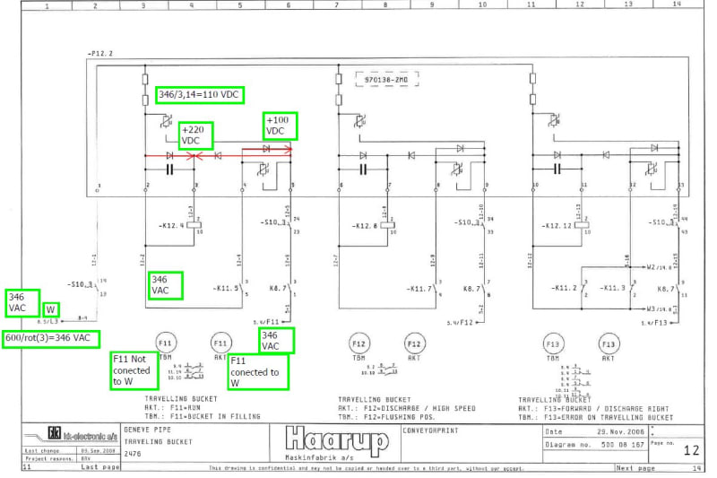
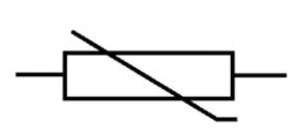
I am working on installing this new system for a company and there is some confusion on what this component is. The original manufacturer is out of business, and has been for a while. I cannot find any information on the part or anything. Its like a ghost. So, according to this print I am to wire 3 phase, 480vac to UVW. Now, they are sending a and b phase to power the primary side of a control transformer (pg8). C phase (L3 in the print) they send to terminal 1 on the unit in question (pg 12). F11, F12 and F13 are inputs associated with each sub-circuit of the device and close the associated relays corresponding to their respective outputs (k12.4, k12.8 and k12.12). These relays tied to these outputs are 110 VDC coils, so I am assuming that this component (page 12) is some sort of rectifier that takes 277vac signals and rectifies them for use within this system. Their people (who have never worked on this machine) are telling me I am to put 24vds signals to f11, f12 and f13. I don't see how that is possible with 277vdc being common between all 3 circuits inside of the component. I'm not quite sure what the blank boxes are at the top of each circuit, within the component (pg 12), or the box with the line through it diagonally (pg 12). when I TEMPORARILY jump 277v to F11, f12 and f13 those relays energize. Have any of you guys seen this circuit before, and what are the two symbols (besides the diodes and N.O. contacts in each subsystem in the component?


