Continue to Site

Eng-Tips is the largest engineering community on the Internet

Intelligent Work Forums for Engineering Professionals

  • Congratulations waross on being selected by the Eng-Tips community for having the most helpful posts in the forums last week. Way to Go!

High ampere and low flow problem 4

Status
Not open for further replies.

terrorist

Mechanical
Aug 29, 2013
18
We have one newly installed pump. Its a between bearings, axially split casing, single stage centrifugal pump. Suction is from a flooded tank. Pump is tripping at overload even at a flow lesser than 50% of the rated discharge. Saw its power curve. Input power vs flow curve slopes downwards. Is it possible for any pump that on increasing its dis flow, it starts taking lesser current? If its possible, kindly advise how to start such a pump.
 
Replies continue below

Recommended for you

I agree with Walt (good point!).
Here is some general info about expected shape of bhp vs flow curve for various types of pump.
faq237-1543
I don't associate that pump curve with that type pump you have... very skeptical that they match.
Maybe you're working off a pump curve that does not correspond to the installed pump (and if there is incorrect pump data floating around, maybe it was used to set your overloads).

=====================================
(2B)+(2B)' ?
 
Are the cables adequately sized?

To a crude first approximation an induction motor is a constant power load over a small range of speeds, so if the terminal voltage drops then the current goes up to compensate. Long cables can be fine from a thermal rating (i.e. they won't melt when carrying operating current) but introduce signficant volt-drop between the source and the motor. Get someone fresh to this problem to run the cable sizing calcs.

Make sure the source itself is healthy too - the MCC should at least have a voltmeter. See how far it falls when you run the pumps.
 
Your pump technical documents do not match.

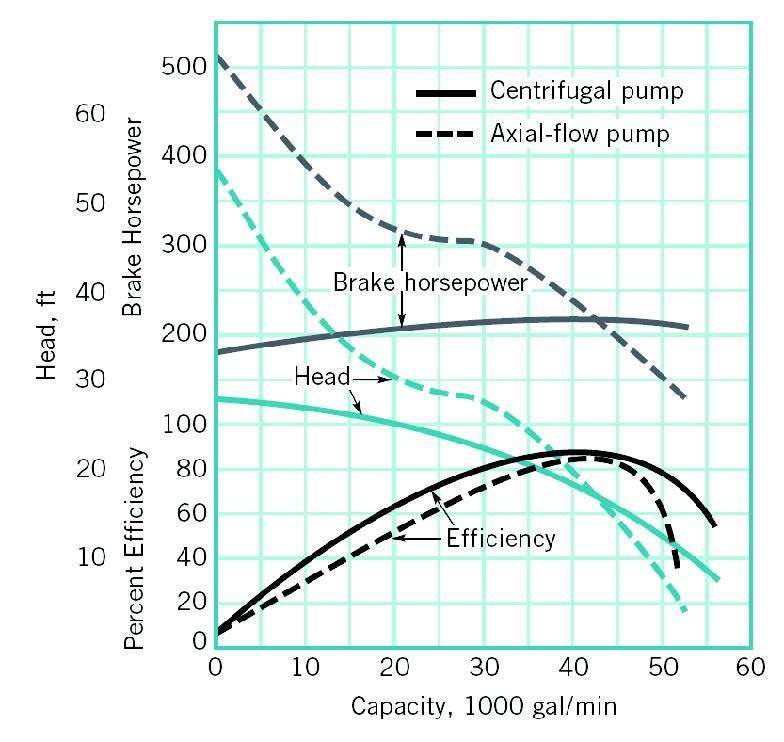
The pump curve that you have presented is for an axial-flow pump. However, the drawing shows a split case pump.

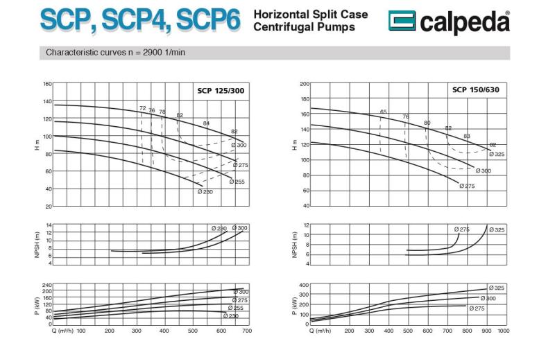
Compare the pump curves:

fluid12_fqspou_bwrvyl.jpg


Here is another pump curve from a spilt case pump.

pump_curve_eiylgo.jpg


Please present the pump curves with the pump model number on them.
 
As usual too many unknowns to get a clear picture, the comments re the rising power curve is just a further query in the mix as is the data sheet which specifies side suction and top discharge.
The pump manufacturer and model might clear some of the misunderstandings


It is a capital mistake to theorise before one has data. Insensibly one begins to twist facts to suit theories, instead of theories to suit facts. (Sherlock Holmes - A Scandal in Bohemia.)
 
Confirm that the 3 pumps operating in parallel are all the same. If not they will be fighting each other.
 
Either the OP has passed away,too busy to reply, too embarrassed to tell us what the problem was or there wasn't any real problem.
Just chalk it up to another wheel spinning exercise.

It is a capital mistake to theorise before one has data. Insensibly one begins to twist facts to suit theories, instead of theories to suit facts. (Sherlock Holmes - A Scandal in Bohemia.)
 
Status
Not open for further replies.

Part and Inventory Search

Sponsor