Eng-Tips is the largest engineering community on the Internet

Intelligent Work Forums for Engineering Professionals

  • Congratulations waross on being selected by the Tek-Tips community for having the most helpful posts in the forums last week. Way to Go!

High pressure angle gears used as a bearing subject to a large radial load 1

Status
Not open for further replies.

pf26

Mechanical
Sep 4, 2020
9
0
0
FR
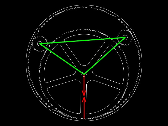
I want to use an inner/outer gear couple to replace a very large ball bearing, mostly radially loaded (it is a wheel hub)
Because of the load direction, it seems wise to increase the pressure angle, as it puts the load forces more perpendicular to the tooth surface and also because it increases the radius of the tooth profile, hence increasing the Hertz surface of the teeth contact.
Increasing PA comes at the cost of reducing the teeth height, but who cares when the torque transmission requirement is low.
To put a few numbers: ring gear diameter 240mm, inner gear 190mm. Aluminum 7075. extreme radial Load: 4000N
The outer ring gear is also guided by 2 other smaller gears (32mm diam - this probably determines the minimum tooth module).
Question is how to select the optimal tooth design for the case ? Would there be a problem to use as high PA as 45 degrees ?

You may wonder why I don't simply use a large roller into a ring. But under some conditions, the radial load may decrease to the point where the friction would not suffice for the little torque transfer needed, so I really need teeth.
Thanks ! Pierre
 
Replies continue below

Recommended for you

Is it possible to use a large roller into a ring to handle the radial load and a small gear pair next to it to handle the torque?
 
When the pressure angle gets larger than 30 degrees, there becomes manufacturing issues. The root apexes and tips,
What AGMA class is been considered?
If ground it really becomes a problem.

It's my understanding as the pressure angle
Becomes larger there is more radial force.
Will these be just cut gears or also ground.
Shoot some numbers here and let's run the numbers.
 
Thanks for your suggestions. Indeed, it might be easier to manufacture using a large roller and more standard gear pair.
But I forgot to mention another point: there are also other loads: axial and torque (about a vertical axis) - these loads must be handled but it does not matter very much if they result in higher friction and some wear, because they occur not that often.
Ideally, the gears would be cut as herrigbone to make it self centering, able to resist other loads, and noise free.

I am not familiar with AGMA classes and gear fabrication. Obviously the cheaper the better, max 1000$ for a single 4 gears set, maybe <400$ per small batches. Using aluminum 7075, it requires a lifetime of >2000hours at approx 400N radial load (1/10 of extreme).
I was thinking of 5axis cnc machining - I doubt there are existing tooling for such funny gears.
Hopefully they don't need to be ground, but I must admit I don't not precisely the implications.

I calculated the Hetz surface and pressure for a 6mm thickness - R=70mm (curvature of the tooth profiles, nearly the same for inner and outer) and found po = 467MPa - which might be acceptable for extreme load on al 7075 ?

Just a picture to show the internal gears attached to a common green frame, and main load in red.
gear_only1_tfucss.jpg
 
Application is a wheel hub for a recumbent bicycle (there will be sprokets attached to the ring gear). The idea is to have the crank pass through the hub, above the large inner gear (an alternative configuration is to have the crank pass through the wheel axis, but this makes it positionned too low, thus having pedaling unconfortable)

" as the pressure angle becomes larger there is more radial force" .. due to the applied torque. In my case, the torque is relatively small, so the radial force resulting from that torque will be generally much smaller than the external radial load (due to the weight applied on the wheel through the hub).

As the pressure angle is beyond 45degree (which make >90degree at the teeth roots), it seems easier to CNC cut the teeth, don't even need a pencil-shaped end mill ?
 
The other concern is that 45 deg. PA are normally for splines, I never cut a 45 Deg. Pressure angle for gear teeth, That it may not roll properly, Max Involute I cut are for pump gears @ 30 Deg.
you may have to run a some some test parts, and see how they roll, on 45 Deg. Pressure angle the tooth thickness changes quick, draw up the teeth and adjust to get the sweet spot to manufacture.
far as milling it depends on the type of tool, a wheel cutter will tend to apex at the Outside diameter of the cutter, and may dull quickly, so truncate the OD of the parts, and raise the minor diameter
to give more tooth tip and bigger flat at the root. this in turn a larger width at the wheel cutter, I believe it's doable. since this is low stress and RPM,
 
Thanks for the link. Unfortunately not so easy to find documentation on very high PA gears.
I tried the animation on my gear designer, and it seems to roll. Here go the screen captures
[link omegawatt.fr/paille/gear2.mp4]HighPA_gear_anim[/url]
[link omegawatt.fr/paille/gear1.mp4]HighPA_gear_anim_detail[/url]

I am not so sur I understand where I should truncate. My gear generator has an "addendum" option for both both gears. I set them to 0.3. Lowering this value truncates the teeth, but I am not so sure it would be easier to manufacture.

Before I contact manufacturers, I also need to extrude the 2D gear profile. For a herringbone gear, I should extrude with a linearly variable angle first going up, then down. Instead of linearly varying, I could use half a sinevawe function - (instead of the triangle used for herringbone), to avoid the sharp transition ?
If don't think the CAD packages I sometimes use (Qcad, Freecad, Design Spark, skechup..) can help me with this kind of funny "variable angle" extrusion.
 
to draw gears correctly you need professional gear software, there is a bunch out there, and not that expensive, or research how to draw it manually with cad, but based on base diameter.
the animation you drew, I am afraid will not suffice. good luck
 
I used a hobbyist gear generator ( Now I checked the .dxf file, and it seems accurate, the teeth profile is approximated with segments, and I measured there are enough segments to limit the error to less than 0.005mm.
Anyway, I am interested in a low cost professional gear soft if you can recommend me one.

Finally, as I could'nt find a suitable CAD soft for variable extrusion, I tried to produced the .stl from scratch (in VBA Excel / I've already played with that some time ago).
3Dsine_144_120_quv08w.png

I will try to have them 3D printed in Nylon, to check how it behaves. I had a quote for less than $100, but it takes a while..
 
pf26,

I designed a pre-loaded gear drive using conventional gear profiles. One of the gears was custom made. The fabricator told me afterwards that they could have cut the gears oversized so that there would be zero clearance in the gear profiles. If gears are fixed in position, you need a clearance, and the gear profiles should be cut for optimal performance with the clearance. You want your gears to run smoothly at zero clearance.

--
JHG
 
Thanks. I will check the software.
Regarding clearance, we consider have one gear adjustable in position, so there should be no need for clearance in the tooth profile. Also, using aluminum and relativeley thin section, there will be some deformation, thus more clearance - we need to take care than under no circonstances, the ring gear can be pulled out of the 3 internal gear set.
 
Status
Not open for further replies.
Back
Top