Eng-Tips is the largest engineering community on the Internet

Intelligent Work Forums for Engineering Professionals

  • Congratulations waross on being selected by the Tek-Tips community for having the most helpful posts in the forums last week. Way to Go!

Highly Viscous Non-Newtonian Pipe Flow to Dispensing Nozzle Calculations

Status
Not open for further replies.

Geordil

Mechanical
Jul 25, 2018
19
0
0
US
Hello everyone,

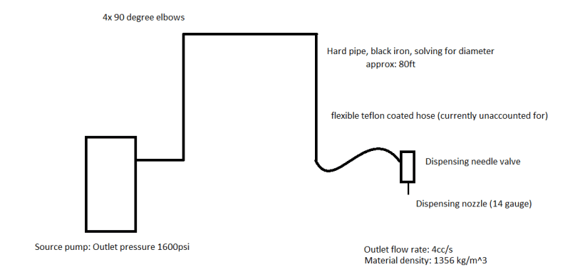
I'm working on a problem in which I am trying to recommend a hard pipe diameter to a customer for a (relatively) high viscosity non-newtonian fluid.

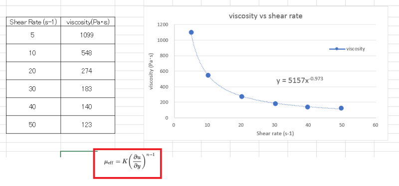
I am treating it as a power law fluid and have obtained constants K and n to describe the viscosity in relation to shear rate. I also have desired discharge flow rate, inlet pressure (outlet pressure is zero, right? It's being dispensed from a nozzle.), approximate pipe length, and nozzle size.

I've written some python code in order to help my calculations and here's where my issue is coming in. The Reynold's number I'm getting is on the order of 10^-6 which raised a red flag, and, my friction factor is about 9,000,000 so another major red flag. I am using 64/Re for the friction factor calculation. Using a different equation for friction factor like colebrook can give me a more reasonable friction factor, but doing so also yields a suggested pipe diameter that is far too small (based on practical experience).

Anyway, I'm not sure if I'm approaching this problem right at all, as I'm treating it as almost entirely a pipe flow problem. I think I probably don't have the right terms in my equations to account for the heavy neck down to the 14 gauge nozzle, but I can't seem to dig up any relevant information.

Here is my code:
Python:
import sympy as sp
import numpy as np

delP = 1.1032 * (10**7)  # Pascals
rho = 1355.92  # kg/m3
Q = 4 * (10**-6)  # m3/sec
L = 24.38  # m
n = 0.027  # constant obtained from viscosity vs shear rate plot
K = 5157  # constant obtained from viscosity vs s   hear rate plot
# D = sp.symbols('D')  # diameter with inches to meter conversion factor
d = sp.Symbol('d')  # inverse diameter (inverse because solver is having problems with D in denominator)
pi = np.pi

v = Q/((pi/4) * ((1/d)**2))
# average velocity expression from flow-rate and diameter
Re = ((((1/d)**n)*(v**(2-n))*rho)/(K*(((1+(3*n))/4*n)**n)*(8**n-1)))
# Reynolds number expression for power law fluids (darcy friction factor)
# f = 16/Re
f = 64/Re  # Darcy friction factor

k11 = 798.9  # Friction loss factors
kinf1 = 0.3939
k12 = 300
kinf2 = 0.1
k13 = 1000
kinf3 = 0.25

kf1 = (k11/Re) + kinf1*(1+d)
kf2 = (k12/Re) + kinf2*(1+d)
kf3 = (k13/Re) + kinf3*(1+d)

inv_diameter = sp.nsolve((-delP/rho) + (2*f*(v**2)*L*d) + 4*(kf1*(v**2)/2) + (kf2*(v**2)/2) + (kf3*(v**2)/2), d, 1000)
#  Solving for inverse diameter
d = inv_diameter

D = (1/inv_diameter)*39.37  # Diameter, in inches
v1 = Q/((pi/4) * ((1/inv_diameter)**2))  # velocity in mm/s
Re1 = ((((1/inv_diameter)**n)*(v1**(2-n))*rho)/(K*(((1+(3*n))/4*n)**n)*(8**n-1)))  # Reynolds number
f1 = 64/Re1  # Darcy friction factor

print('Velocity in mm/s is ', v1*1000)
print('Reynolds number is ', Re1)
print('The friction factor is ', f1)
print('Pipe diameter in inches is', D)

Which results in:
Python:
Velocity in mm/s is  1.06398183679041
Reynolds number is  6.58862657597730e-6
The friction factor is  9713708.80743941
Pipe diameter in inches is 2.72385109750467

all of which seems reasonable except for the friction factor and Reynold's number of course, but I'm looking at it from my undergrad fluids perspective where we never looked at fluids this viscous or flows this slow.

Any help or tips would be greatly appreciated!

Thank you.
 
Replies continue below

Recommended for you

It's good to see your interpretation of your real word problem into numbers, math and code, but can you describe your real world problem please. A lot of us have software that we may be able to use to double check your results very quickly, if only we knew what was going on physically. A sketch, dimensions, P&ID, etc. would be helpful.

Good luck,
Latexman

To a ChE, the glass is always full - 1/2 air and 1/2 water.
 
Latexman: of course, my apologies. Attached is an illustration that should help matters.
Untitled_fj2kh4.png
 
My interpretation here is you have fluid of unknown, but high viscosity (how high is high?), going 25m at some very low flow rate (14.4 litres/hour?) flowing in a constant flow through some sort of nozzle ( 14 guage?? - which is ?mm?) to atmosphere with just over 100 bar (10MPa) at the far end.

Correct?

Remember - More details = better answers
Also: If you get a response it's polite to respond to it.
 
LittleInch: your interpretation is pretty much spot on.

To clarify:
[ul]
[li]Viscosity is variable as it is a shear-thinning fluid. Power law fluid constants n = 0.027 and K = 5157 fit the available shear rate vs viscosity data well[/li]
[li]14 gauge = 1.6mm inner diameter[/li]
[/ul]
 
Well flow rate is your first error - 4 cc = 4 x 10⁻⁵m3/sec or 144 litres per hour. There'ss 100 cc to a litre and 1000 litres to the m3.

What is your shear rate at your typical velocities? or shear rate at 1", 2" 3" etc?

At this flow your shear rate in the main tube is going to be very low and hence viscosity sky high

I think an issue you have here is that you're deep into laminar flow and I don't know how that works as well as turbulent.

Think you need to run a few options for different line sizes and then figure out the pressure drop.

Remember - More details = better answers
Also: If you get a response it's polite to respond to it.
 
Is the teflon coated hose a smooth, "straight" bore or corrugated? If corrugated, how corrugated?
More details on dispensing valve. Cv? K? Make, model.
More details on dispensing nozzle. Make, model, 14 guage for how long?

I have a power law pressure drop spreadsheet, so should be somewhat easy once a K value can be assigned to the above.

Good luck,
Latexman

To a ChE, the glass is always full - 1/2 air and 1/2 water.
 
So far . . .

80 ft pipe
4 elbows
1 globe valve
1 exit though 1" of 14 gauge hole
no hose

3" Sch 160
1400 psi

2" Sch 160
2100 psi


Good luck,
Latexman

To a ChE, the glass is always full - 1/2 air and 1/2 water.
 
LittleInch:
Thank you very much for your input. I would love to get some more testing done, but we don't have a lot of capability for such things in house. We supply the dispensed material primarily and the dispensing equipment secondarily. Piping and such isn't something we sell or integrate with, but it would be nice to be able to have these kinds of conversations with customers.

Latexman:
The teflon hoses are smooth bore. I would say 3m long in this application.
No information available about Cv or K values for the dispensing needle valve. My company is the manufacturer, but those details are not in the literature.
14ga nozzle is 13mm sus nozzle from iwashita.
Pipe is likely to be schedule 40 or 80.

Thank you!
 
Has the ID of the hose been decided (what is it?), or can it vary like the pipe diameter?

Good luck,
Latexman

To a ChE, the glass is always full - 1/2 air and 1/2 water.
 
Is this continuous flow or intermittent?
If intermittent then how long will it take to re-establish flow and get thinning?
When the line is static won't you have the high viscosity?
We had a line of similar fluid that recirculated so that we never had to start against a line full of 'dead' fluid.
And we didn't try to take it 80'.

= = = = = = = = = = = = = = = = = = = =
P.E. Metallurgy, Plymouth Tube
 
Agree with EdStainless. Consider installing a recirculation loop so the pump is not deadheading. Use short pipe takeoffs from the recirculating loop to the dispensing nozzles,
 
Dave,

You might benefit with reprints from Chemical Engineering magazine by M. H. Wohl. It is titled, "Designing for Non-Newtonian Fluids". They appreared Jan. 15, Feb. 12, March 25, April 8, May 6, and June 3, 1968.


Good luck,
Latexman

To a ChE, the glass is always full - 1/2 air and 1/2 water.
 
According to my companies pipe specs you need Steel XS Seamless for a cyclic service.

10' of 3/8" ID smooth wall hose will have a pressure drop of ~ 1130 psi by itself. Add that to what I said above about the other components.

You should rethink your spacing, or do something to reduce viscosity (increase temperature?), or both.

Good luck,
Latexman

To a ChE, the glass is always full - 1/2 air and 1/2 water.
 
Edstainless/bimr: It is an intermittent flow, and that makes me think of it a little differently. Realistically the pump will go through a drum or two of the material just to fill and pressurize the pipeline and establish an air-free dispense. Then it will be "bled off" in 60cc or so increments every 30 seconds, depending on the cycle time on the line, while the pump just works to keep pressure on the pipeline. Barely a flow problem at all, just kind of a long pressure vessel. Recirculation is a very interesting idea that I will discuss with plant engineers, might save some wear and tear on the pumps at the very least.

Latexman: Thank you again, and very much, for your help. I will try to dig up those reprints as I'm sure this will not be the last time I need to approach a problem like this. We have experimented with heat wraps on the hoses in the past with varying measures of success. I think the big factor that changes things is the intermittent properties of the flow. So the dispensing nozzle discharges its 60cc on a part, then the pump immediately cycles and discharges its 60cc into the pipeline. And I'm pretty sure some places control the pumps through a PLC so when the system pressure drops to a certain point, the pump kicks on.

Anyway, I really really appreciate everyone's help, input, and patience. This is my first engineering job out of school and I have a lot to learn.
 
Status
Not open for further replies.
Back
Top