Eng-Tips is the largest engineering community on the Internet

Intelligent Work Forums for Engineering Professionals

Hips, valleys and load points 5

Status
Not open for further replies.

Bammer25

Structural
Mar 22, 2018
135
0
16
US
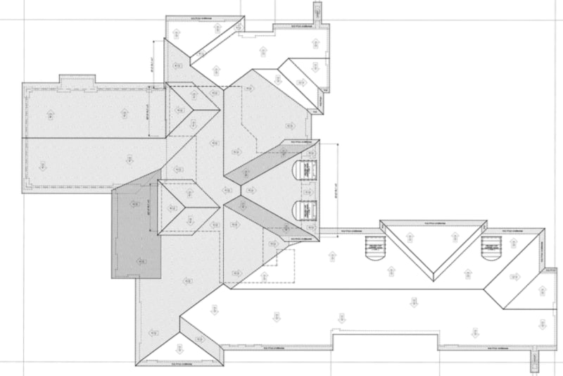
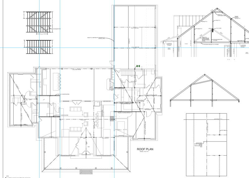
Designing a house with a complex roof. Such fun. Anyway, I am constantly arguing with myself over where we need load points at the connections of hips, valleys, and ridges.

I know a lot of it relies on whether or not you have exterior wall thrust. So if I have rafter ties and collar ties I consider the ridge a nailer. But what about when you have a valley and and hip coming in? They can have quite a bit of. Arrival reaction. I know good practice can be just to simply post down and feel good about it. I have seen thousands of times where the framer will just nail them all together with a few boards and it obviously holds fine.

What do you guys typically do?

I ask because I am going to a meeting with the truss company and the builder next week and he is going to want reactions where I have specified load points. If I give him true reactions calculated from my LvL calcs the loads will be astronomical. In some cases we land in walls but others on top of attic trusses where he will never get the reaction to work.
 
Replies continue below

Recommended for you

Show a framing plan where loads are astronomical. I have not found such a case, but I have not a lot of experience in residential framing.
 
A valley member will have vertical reactions that need to be resolved, and these reactions can be quite large. It’s just a function of the geometry of the roof and the load being collected at these points.

A hip, on the other hand, does not need discrete vertical supports as long as it is accompanied by thrust-restraining framing that is properly positioned and connected. I find that on complex residential roofs, because of the architectural concept of the space below, hips often need to be designed as vertically-supported beams given the absence of space below in which to provide reliable thrust resistance.

Also, If you rely upon membrane action of the plywood-sheathed roof to help resolve and distribute these reactions, you do so at your own significant risk. The chance that the system is properly designed and detailed to accommodate this complex behavior is slim (especially in light of fee and time constraints), and the likelihood that it actually gets built properly (even in the event that it was designed properly) is even slimmer.

Nowhere is an architect’s (or “custom home designer’s”) apparent disregard for (and/or misunderstanding of) structural load path more obvious than in an intentionally elaborate single-family residential roof volume. The costs they drive into the project with these features are staggering. And look, if that’s what the owner desires, then a good structural engineer is up to the task of resolving it. But there’s always a compromise needed. Some combination of space/depth and cost is always a concession.

If you need columns, you need columns. If the space below can’t accommodate a column, then you need a transfer element that can span between two point where columns CAN be accommodated. Stake your claim on what is needed structurally in order to resolve the architectural roof concept.
 
A few comments:
[ol 1]
[li]I say keep things simple. Just send them the loads even if they are "astronomical." Worst case, the trusses won't be able to support them and you'll need to reevaluate the overall roof framing. Best case, the trusses are fine, and you're done.[/li]
[li]In general, it's possible to design a roof without large framing members at ridges/valleys/hips as long as the outward thrust of the roof is restrained. However, while I have done designs like this, I generally prefer discrete, simple load paths. Designing to restrain the outward thrust is more complex to analyze and generally required more complicated connections, which we all know might not be constructed properly.[/li]
[li]I agree with Seppe that you should not rely on the strength of sheathing to resist outward thrust (roof spreading). In most cases the sheathing will add a lot of strength and is probably the main reason a lot of these non-engineered roofs seem to work, but to quantify this strength seems difficult. You would need to be careful to provide proper detailing at panel joints, panel to framing connections, etc. [/li]
[/ol]

Do you have a general sketch of the roof?
 
Here is plan view of the roof. As you can see there’s a lot
IMG_8974_c15ioz.jpg
 
Good lord... That is the most complicated roof I have ever seen.

I agree with Seppe and Eng16080's comments. Stick to your guns and try to keep your analysis and load paths simple at the onset for consulting with the truss supplier. Hopefully, they can stomach what you bring to the table at this stage.

Godspeed, solider.
 
Yup, that roof sucks.

For locations that don't have cathedral ceilings, often the trusses can clear span and essentially fake all this elaborate geometry. I'm guessing it's not that simple here though.

I'm sure this house will look cool and all, but such a complex roof will likely be a maintenance problem years to come.
 
Yuk. This is what happens when an Arch. creates a floor plan and then tries to fit a roof on it.
I'm working on a similar one now that is being stick framed and is very steeply pitched so the support posts are really long.

 
That roof is only complicated if they want vaulted ceiling. If ceilings are flat, just send it over to truss manufacturer and done! That looks like a type of roof using truss system.
 
Agreed that just about any complex roof can be solved with prefabricated trusses provided the ceiling plane is flat. But I think it’s implicit in the OP that flat ceilings are not the case here, hence the questions about concentrated loads and concern over their magnitude.

If I’m an architect looking to make waves by ratcheting up the looney tune factor on the exterior profile/geometry of the roof surfaces, I probably carry that philosophy right on through to the ceiling planes as well. I do love me some prefab trusses, but their feasibility takes a big hit when the architectural design is full of geometric pinch points.
 
Seppe, I would have asked the architect before I give them a proposal. There is no way I would touch that project if it was stick framed. Architects need basic understanding of structural framing.
 
XR250, that is crazy! I only see one gable where you can post down a ridge. I have a feeling the chance there is an interior wall to post down for the ridge and lined up with the floor below is slim to none.
 
Dbl. Stud said:
XR250, that is crazy! I only see one gable where you can post down a ridge. I have a feeling the chance there is an interior wall to post down for the ridge and lined up with the floor below is slim to none.

Here is one I am currently working on. Not quite the mess the OP's is. Was not too hard to find bearing. Just have to be creative. The roof pitch varies from 12:12 to 16:12 - gotta love these Arch's!
mess1_vopino.png
 
I did another one worse than this a few weeks ago. These roofs are such headaches. Not like with a beam you can just add some fluff and sleep better. What a nightmare.
 
I do roofs like these all the time and around here most things are stick built when an Arch and Eng are on the project. I tie the roof and use ridge boards where I can but anywhere that the tie breaks, I design a ridge beam. Also, I always design hips and valleys as structural beams supported on both ends. If the beam sizes are crazy or posts are large, I don't care as there is no solid engineering justification to ignore the thrust (outside of complex and sketchy diaphragm calcs). Obviously tons of roofs disregard all of this but as structural engineers I don't see how we can.
 
Status
Not open for further replies.
Back
Top