Eng-Tips is the largest engineering community on the Internet

Intelligent Work Forums for Engineering Professionals

Holes Centered on the piece 3

Status
Not open for further replies.

CMillanR

Mechanical
Feb 21, 2024
2
0
0
MX
Hi, I'm new to this forum.

I'd like to know the simple way to represent that holes in the image are centered. Should I use centerlines or dimensions?

I hope you can help me. Thank you in advance.


Captura_de_pantalla_2024-02-21_160201_x1rq0o.png

Captura_de_pantalla_2024-02-21_160444_pp11kb.png
 
Replies continue below

Recommended for you

Centerlines, because of the rule that there is an implied basic zero dimension when center lines and axis lines are shown aligned on a drawing. Since hole locations should be basic and conrolled by geometric tolerances, showing the center lines aligned is enough to imply a centered true position.
 
Should use GD&T:
Make dim 15.00 datum feature and position hole w.r.t. datum.

"For every expert there is an equal and opposite expert"
Arthur C. Clarke Profiles of the future

 
CMillanR,

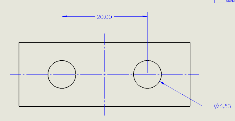
Your top image is simple and very clear. The centrelines indicate that everything is symmetric.

Consider your tolerances. I do stuff like this all the time, where I call up the mount face as the primary datum, and the holes as the secondary datum feature. I apply a fairly sloppy profile tolerance all around. My assumption is that the holes must clear fasteners, and that the outline is not critical.

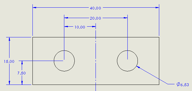
In alternate situation, the relationship between the holes and one or two edges is critical. My secondary datum feature probably would be the long edge, and my tertiary datum feature, the short edge. I would make the thing asymmetric as a poka yoke to assure that the datum features are used for location.

You have requirements. Meet them.

--
JHG
 
So many GD&T examples are rectangular plates with some holes in them. I always wonder what they are for and whether someone actually gets a salary for designing them.
 
Hi, CMillanR:

Label bottom of the part as Datum A.
Label dimension 40 as Datum B. This dimension needs to be BASIC.
Label dimension 20 as Datum C. This dimension also needs to be BASIC.

Position two holes of Dia. 6.53 as a pattern.

Best regards,

Alex
 
The top image is acceptable. The second image is not yet a lot of people mistakenly think that you need a dimension from the centerline to maintain symmetry, (the 10,00 in your case) but that actually almost guarantees that the holes will not be symmetrical because that dimension from the centerline has a tolerance as well. The best way to do it is to use GD&T and define the overall length dimension of 40,00 as a datum. This creates a datum plane in the middle. Then set the hole locations as basic dimensions and use positional tolerancing to define how symmetrical the holes need to be in relation to the overall length datum.
 
Thank you all for your insights and suggestions.

I truly appreciate your help in resolving this lingering question I had.

I understand that centerlines can be used, but as you say, it's better to use GD&T to locate the hole positions.

I'll definitely be putting all of these suggestions into practice.

Thanks again!
 
Status
Not open for further replies.
Back
Top