Continue to Site

Eng-Tips is the largest engineering community on the Internet

Intelligent Work Forums for Engineering Professionals

  • Congratulations KootK on being selected by the Eng-Tips community for having the most helpful posts in the forums last week. Way to Go!

Hopper-Transfer Chute Extrusion Screw, Vertical Pressure

Status
Not open for further replies.

Doodler3D

Mechanical
Jan 20, 2020
188
Hi,

Would it be appropriate to use the Janssen or Jenike equations to calculate the vertical and wall pressure at the base below the extrusion screw? I'm assuming the presence of the screw blades would increase surface area and significantly decrease the vertical pressure on the base. A hydrostatic assumption leads to design failure and additional reinforcement.

Thank you
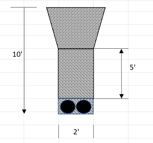
Screenshot_410_w0uh4q.png
 
Replies continue below

Recommended for you

I regularly design such configurations. Though I don't really understand your question. But my answer for a question that I don't understand.

The design load should broadly include the normal static and flowing pressures and nothing more complicated than that.** The presence of screw blades surface areas doesn't change the pressure values, well at least in a way that isn't a reduction in pressure on the bottom of the hopper.

**Plenty of other complications if you really want to dig deeper, eg risk of eccentric discharge...
 
human909,

Basically, the client does not have the external and friction angles for the product and the FEA report provided uses a massive element size leading to a safe design. I re-ran the FEA with a mesh convergence and it fails at the screw extruder if I assume that the contents are hydrostatic in nature. I believe using Janssen/Jenike/Walkers equations would give enough design margin to not worry about failure at the base of the screw, with 10' of material above it.
 
Doodler3D said:
if I assume that the contents are hydrostatic in nature.
Yes assuming hydrostatic will vastly increase your forces. At an extremely rough guess it will increase the pressure by about 50% based on those dimension.

Doodler3D said:
I re-ran the FEA with a mesh convergence and it fails at the screw extruder
Also given the scale of this I could readily see sheet metal hoppers failing in FEA but working in the real world. Thin walled behaviour of steel sheet can readily start acting closer to a thin walled tension member. Whereas FEA you could get excessively high bending forces that won't occur in reality not to mention stress hot spots at the corner.

The Eurocode for silos is the best reference IMO for suitable design loads:

It is far more current than the US or other codes I've seen.


Also note that like most structural loads all the codes are still relatively conservative. Just because it hasn't failed yet doesn't mean it won't fail. I've seen structural failures of feeder hoppers. When you have large hoppers and 20m+ of product head you can get pressures in excess of 100kPa.
 
Thanks human909 for abating my concerns. The design failed by elastic, limit load and elastoplastic FEA and got me perplexed.
I've been using the Blodgett-Troitsky-Gaylord books for reference and hand calcs. I'll dig deep into the Eurocode and convince the manager to take that route.
 
No problems.

Note;
10 foot of product with a 2 foot wide hopper won't normally end up with crazy high pressures. Most of the time the design will be driven by other strength requirements like robustness. So I'd expect that whatever they have going on there is likely sufficient. However with larger inscribed diameters and an product head as 10x or more of the high pressures really do dominate design.
 
Status
Not open for further replies.

Part and Inventory Search

Sponsor