Continue to Site

Eng-Tips is the largest engineering community on the Internet

Intelligent Work Forums for Engineering Professionals

  • Congratulations cowski on being selected by the Eng-Tips community for having the most helpful posts in the forums last week. Way to Go!

Horizontal bridging in pre-engineered wood trusses (residential) 4

Status
Not open for further replies.

PSUengineer1

Structural
Jun 6, 2012
151
looking to start a brief conversation on the importance of installing specified horizontal bridging members between pre-engineered wood roof trusses.

let's start with this question...
what is the importance of installing horizontal bridging between trusses with the ends of the bridging members setting at third points of the web members that they are attached to? Is this to provide lateral stability in the z-axis?...or it cuts down the unbraced length of the web member that it attaches to? Pre-engineered designs are computer generated and the results are often not able to be confirmed by the "back of the envelope" method. I just want to "firm-up" my understanding of modern day pre-engineered wood roof truss design.

thx.
 
Replies continue below

Recommended for you

Serves to laterally support the bottom chord and serve as alignment mechanism for the bottom chords for sheet rock installation as well as vertical alignment.

Mike McCann, PE, SE (WA)


Bracing is usually required to reduce the unbraced length of the web member and prevent buckling about its weak axis. The horizontal brace is not sufficient by itself to prevent buckling because all connected web members can buckle in the same direction with the brace simply translating perpendicular to the truss. In addition to the bracing member, some diagonal members are required to prevent translation.

BA
 
I agree with BA. I misread the post.

Mike McCann, PE, SE (WA)


As with all of my posts, Canadian context warning. Curl up to the fire, grab a bottle of your favourite adult beverage, and settle in - for I shall tell you the story of bracing.

This is something I've been reading into a lot lately too. For some reason in my area it was very loosely enforced by inspectors, but now it is getting cracked down on hard. I suggest looking into, 'BCSI-B1C: Guide for Handling, Installing, Restraining & Bracing of Trusses' (
OK, so first off we have the two different types of bracing: Member bracing, and Permanent Bracing.

Individual Member Bracing
This is what you are referring to. It can consist of lateral members spanning in-between trusses, T or I bracing on individual members, sheathing, or metal strapping.
The main purpose for this type of bracing is to reduce the bucking length of the individual truss members, and to assist in erection / spacing of the trusses.
It is important to note that these are usually automatically generated by the truss design software and can sometimes be wildly impractical (like mid-span lateral bracing on a sheathed Party Wall Truss). A good designer will catch it early - but there are usually alternative means.

truss-failure_qjjwnv.jpg

This is a truss failed by individual member bracing. Note that the later bracing only spans from one member to another - providing very little actual resistance to buckling. It should be noted that this failure can still occur with continuous lateral bracing & this is why the permanent bracing is vital.

Permanent Bracing
This is the one we are responsible for. The permanent bracing is not the responsibility of the roof truss designer, and this is made very clearly in the opening remarks of, 'Truss Design Procedures and Specifications For Light metal Plate Connected Wood Trusses' by Truss Plate Institute of Canada.
The permanent bracing is designed to ensure complete stability of the roof system and consists of 3 main components:
Bottom Chord Bracing
-Lateral bracing running perpendicular to trusses, spanning 10'-0" oc typically, and running the full building length. It ensures no excessive displacement of trusses. Typically 2x4 but 1x4 can be used.
-Ceiling plane sheathing can be used as a substitute but it should be noted that the building may be sitting a long time without ceiling plane sheathing installed.
-Zig bracing of the bottom chord is also suggested, this is a diagonal member that runs between the full length lateral bracing. 20'-0" oc (every 2nd lateral). Serves the purpose of avoiding lateral racking of the roof.
Web Bracing
-any web that has a lateral braced spec'd in the truss drawing shall have one set of cross braces spanning at least 4 trusses running from heal height to maximum truss height. In addition the vertical web closest to the centre shall have the same. This is to prevent vertical racking of the truss system.
Top Chord Bracing
-Typically this is the roof deck sheathing, but in absence of sheathing for extended periods provide lateral bracing in the same manner as the bottom chord bracing.

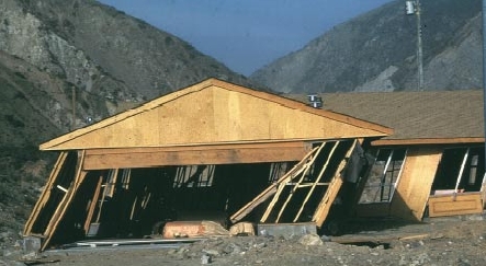
apa_racked_house_hmc10m.jpg

This is a good example of racking, it just isn't in the roof though (my google-fu is off today). As you can see the members maintain their individual spacing, but have failed to remain in plane. This can happen vertically as shown, or laterally under certain conditions.
 
All three planes; bottom chord, web and top chord planes, need to be laterally and diagonally braced. As mentioned above, BCSI Handbook explains it all.
 
Signious said:
Permanent Bracing
This is the one we are responsible for. The permanent bracing is not the responsibility of the roof truss designer, and this is made very clearly in the opening remarks of, 'Truss Design Procedures and Specifications For Light metal Plate Connected Wood Trusses' by Truss Plate Institute of Canada.

EOR Caution:

Individual Member Bracing is also permanent bracing. The truss manufacturer may be responsible for telling us where it is required, but the EOR is responsible to ensure that it is installed so that it effectively reduces the unbraced length of the member. This includes providing such additional bracing as may be required to prevent the bracing member from translating. In my experience, such additional bracing is not shown on shop drawings and often becomes a point of contention when the Contractor is required to supply material and labor for members which are not shown on any drawings.

BA
 
@BA

I know that fight well - and it usually ends up in a change order charged back to the client, and then the client gets on the horn with the EOR to give hell.

We have started sending out a trimmed version of that BCSI handbook with our quote package so expectations for roof bracing before our Sched. C goes out are known by all.
 
An engineering firm here in VT was found liable last year when a roof collapse happened during construction. A number of workers were injured. The collapse was due to insufficient bracing. The EOR was inexperienced, according to the media report.
 
One frequent problem is that the contractor installs a continuous 1x4 or 2x4 ribbon nailed to each web member as shown on the shop drawings and thinks he is finished. He does not realize that those members are not effectively braced when they are tied to each other. They can all buckle in the same direction and need additional bracing to prevent translation. I never really found a good way to convey that message to the contractor in the bidding stage.

Another problem occurs when adjacent trusses have different web configurations. Shop drawings may indicate a required brace at the third points or midpoints of a web member but if there is not a similar member on each adjacent truss, a continuous ribbon will not work because it can't be fastened to the adjacent trusses.

Those were the two most common problems I found when inspecting wood truss roofs and sometimes it required several inspection trips before they got it right. I can certainly understand how an inexperienced engineer would have trouble.

BA
 
For demonstrating the need of more than horizontal bracing I just show them the picture I had posted above. That roof is toast, and it is because there is no cross bracing to avoid 'the big buckle'.

For different web configurations on individual truss bracings I have done 2 things. First, if it is an easy napkin calc I will change the lateral bracing to a scab, T or I brace on the member, as well as blocking the chords. If it is more complex I will throw it back at the truss designer to come up with an acceptable solution.

 
@Splitrings- Why was the engineer held liable? Did he design the temporary bracing?
I don't know any engineer who designs the temporary bracing for trusses - too complicated and way too much liability.
 
I think it is frequently poorly specified who designs what bracing. I think the truss manufacturer designs all truss related bracing, including braces to adjacent structures to support the trusses, both temporary and permanent, and the engineer designs the adjacent structure to support the truss brace loads.

The truss manufacturer does all braces for the trusses, internal and external, permanent and temporary, and the engineer designs the structures to support the bracing, but none of the bracing.

My opinion.
 
I have never seen the truss supplier design any bracing. They typically show only where their members require bracing with a note about nailing of continuous ribbons or alternatively nailing of a Tee brace. The contractor rarely if ever interprets the notes correctly.

BA
 
I have never designed any truss bracing other than the gable end wall bracing on a recent project. Usually the truss manufacturer supplies the engineered drawings showing location of bracing on webs and the typical BCSI bracing sheet.

If I have to design truss bracing these residential jobs are going to get a lot more expensive for the client.

The biggest problem I have with trusses is that I am usually doing my structural review before the truss package has been designed. I don't have access to the reactions of the trusses, this would be useful when calculating uplift and bearing in particular for girder trusses I end up having to calculate it all manually which takes more time.

A confused student is a good student.
Nathaniel P. Wilkerson, PE
 
Confusion about responsibility between the truss fabricator's engineer and the EOR seems to be an ongoing problem. Ultimately, the client is relying on the EOR to ensure that nothing is overlooked.

BA
 
@medeek

If I am (or my mentor I guess) EOR on the project and I am doing a full structural review - I will make it very clear that I need Floor layouts, beam runs, Roof layouts, and shop drawings for the project prior to sending out my form. They need to layouts for BP anyways, so it isn't holding the process up too much.
 
Status
Not open for further replies.

Part and Inventory Search

Sponsor