Continue to Site

Eng-Tips is the largest engineering community on the Internet

Intelligent Work Forums for Engineering Professionals

  • Congratulations KootK on being selected by the Eng-Tips community for having the most helpful posts in the forums last week. Way to Go!

Horizontal Stiffener to increase beam shear capacity

EngDM

Structural
Aug 10, 2021
452
I'm referencing CSA S16:14 and I'm seeing that for Cl. 13.4.1.1 if you have a stiffened web you have different requirements. Firstly, is it referring to transverse vertical stiffeners or a horizontal stiffener? I've seen horizontal stiffeners used for web buckling but I have not myself specified it.

Is there a CSA reference example that one of y'all may have that would go horizontal stiffeners?
 
Replies continue below

Recommended for you

I was under the impression that the stiffeners discussed in 13.4.1.1 is transverse stiffeners. Check out the commentary, specifically figure 2-14. It shows transversely stiffened webs.

Unfortunately I have no reference for horizontally stiffened webs. I would think that would only improve performance in conjunction with vertical stiffeners so you're making the unstiffened portions of webs smaller so buckling is not a concern.
 
I don't know the spec, but I suspect it is talking about effectively reducing the web size and so increasing the web shear buckling stress. If so it shouldn't matter much whether you reduce "a" or "b", ie vertical or horizontal stiffeners. There should be checks to ensure that the stiffener will resist the web buckling underneath it ... the stiffener size relative to the web thickness, and the attachment of the stiffener to the web.

"Wir hoffen, dass dieses Mal alles gut gehen wird!"
General Paulus, Nov 1942, outside Stalingrad after the launch of Operation Uranus.
 
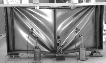
I believe that the stiffeners are meant to be vertical (transverse) and represent a pivot in shear resistance philosophy whereby you permit initial shear buckling then mobilize tension field action (steel strut and tie basically).

Horizontal stiffeners are usually installed to address web buckling arising from flexural axial compression by forcing the web buckling pattern into a mode higher than it's first.

c01_bnkv6m.jpg
 
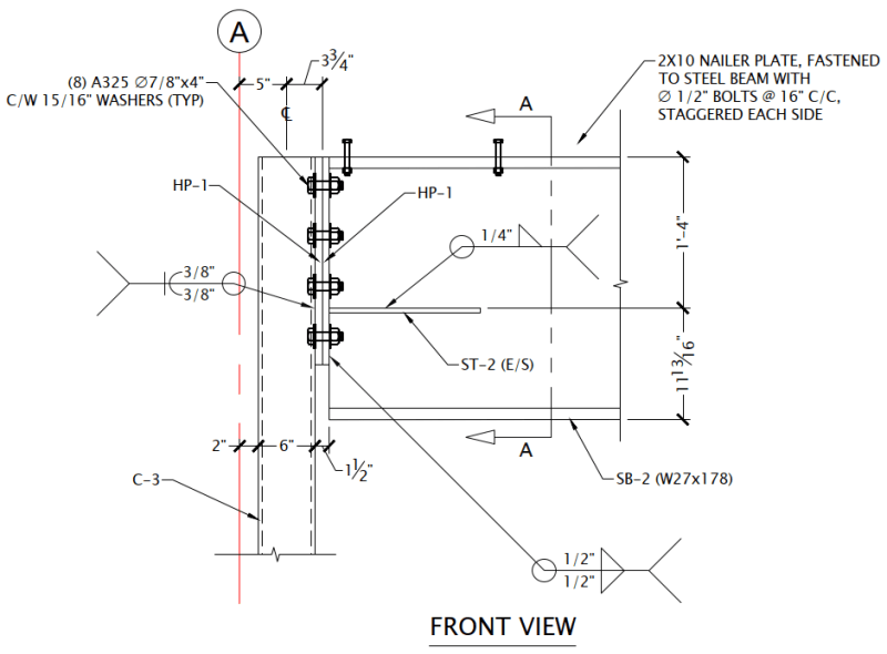
Interesting, any idea what the horizontal stiffener here is doing then? It's a main floor beam, not loaded axially.

1_vkcmxe.png


From what I'm reading, horizontal stiffeners are used to strengthen against web buckling due to bending compression, but being at the end of the member the bending should be nearing zero at a pinned support.
 
Perhaps the designer has anticipated moment transfer at that joint, either intentional or inadvertent?
 
KootK said:
Perhaps the designer has anticipated moment transfer at that joint, either intentional or inadvertent?

Not indicated on the drawings and no design loads were given, nor was instruction on what to design the connections for. RFI's it is.
 
Then my vote is that the stiffeners were detailed to deal with inadvertent flexural compression in the bottom of the connection. I've never done that but I certainly see the logic in it. I would expect the web of the beam to be in flexural compression near where that stiffener is located.
 
KootK said:
Then my vote is that the stiffeners were detailed to deal with inadvertent flexural compression in the bottom of the connection. I've never done that but I certainly see the logic in it. I would expect the web of the beam to be in flexural compression near where that stiffener is located.

Can you elaborate more on where the flexural compression would come from? I mean aside from the connection not being a true "pin", is there another source for it? (Deflected shape inducing compression perhaps?)
 
As usual, albeit it's been a while, I agree with KootK. That connection detail screams moment resistance to me.
 
There is potentially some irony in this. Stop the end plate short of the bottom flange to discourage moment transfer. Put the stiffener in in acknowledgment of some inadvertent moment transfer. Inadvertently encourage moment transfer.
 
That horizontal stiffener is very likely there because the welded end plate does not extend down to the lower flange. And downward bending is going to put a compression stress concentration on the web, and the horizontal stiffener is needed to prevent local buckling of the web. IMO it is a very bad design; the welded plate should extend down to and be welded to the lower flange of the W27.
 
Those type of stiffeners are usually put in to stiffen the web to increase the bearing capacity of the beam web in compression or to stiffen the end plate to increase the tie capacity of the lower bolts but the column doesn't look like it wants to take much moment
 
EngDM said:
Can you elaborate more on where the flexural compression would come from? I mean aside from the connection not being a true "pin", is there another source for it? (Deflected shape inducing compression perhaps?)

I would say that the source likely is from the connection not being truly pinned. The deflected shape of the beam inducing the compression is really another way to say the same thing. And that speaks to how I would normally try to shield the joint from seeing significant moments: making the beam quite stiff such that end rotations were small under a pin support assumption.

When I look at the detailing, it suggests a steel, gravity only frame within a surrounding wood structure. My responses are geared toward that assumption. If this is meant to be a portal frame or something, that changes things.
 
Looking at the beam size (W27x178) and all those 7/8" bolts, it seems like someone is hoping that stiffener somehow helps in shear. The column can't carry much moment, inadvertent or not.

This dovetails with our previous discussions about whether or not the column need be designed for the load eccentricity. I'm sure the 100+ kip reaction would wreck that little HSS6x6 column if the load is applied eccentrically.
 
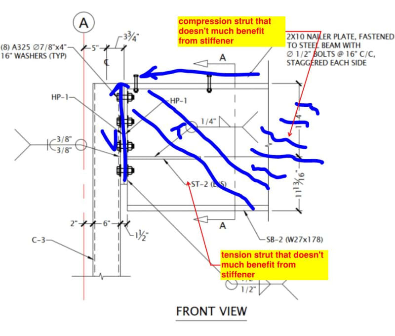
For sport, let's imagine that we knew that the designer's intent was to increase shear capacity. Do we feel that the stiffener would be effective? I see things like I've shown them below.

Do we actually know how long the stiffener is?

c01_trbu7g.jpg
 
Man, 27" beam with like a 13+" width on a 6" column.

Reasons I can think of:
-Just not liking the stiffness variation between top and bottom and eyeballing in a load path they like better
-Wanting to laterally restrain the bottom of the beam more rigidly, maybe being really explicit on detailing to ensure that the beam is laterally and torsionally restrained at the support
-Using the connection to transfer diaphragm forces somehow (no idea to where) so wanting some into the page lateral and torsional stiffness
-Using the connection to stabilize the column off of the diaphragm, so wanting that same lateral or torsional strength
-Restraining a tear-out mechanism of some sort (really don't see it)
-They have a typical detail and they're expecting to cope the beam bottom on some of them
-They have a typical detail and some of them require moment capacity or one of the restraints above
-Detailer grabbing a connection they've used before

Are you sure this thing isn't a diaphragm collector or something?

With just this, my best guess is restraining the column

 
KootK said:
For sport, let's imagine that we knew that the designer's intent was to increase shear capacity. Do we feel that the stiffener would be effective? I see things like I've shown them below.

I imagine it adds to shear capacity in the same way that any flange does

----------------------------------------------------------------------

Why yes, I do in fact have no idea what I'm talking about
 
I think it should be a little longer to be effective. The increase in shear strength is based on the 'buckling' of the web. Having different 'heights' for the web member forces it into a different buckling mode.

-----*****-----
So strange to see the singularity approaching while the entire planet is rapidly turning into a hellscape. -John Coates

-Dik
 
JSN said:
I imagine it adds to shear capacity in the same way that any flange does

You'll have to hold my hand a bit here. How does "any flange" improve shear capacity?
 

Part and Inventory Search

Sponsor