Continue to Site

Eng-Tips is the largest engineering community on the Internet

Intelligent Work Forums for Engineering Professionals

  • Congratulations MintJulep on being selected by the Eng-Tips community for having the most helpful posts in the forums last week. Way to Go!

Hot spot in switchgear 6

Status
Not open for further replies.

poulin76

Electrical
Jan 25, 2017
3
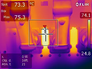
We had an operator send these pictures from the back of a 13KV switchgear main breaker. Myself and a couple other techs were musisng over what it could be. Our guesses are everything from strip heaters to B phase CT. Any one ever see this before or have any good ideas. Thanks.
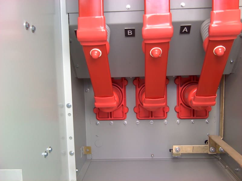
DC_0751_xxyi48.jpg


IR_0796_ezqxgl.jpg
 
Replies continue below

Recommended for you

Hello all,
Sorry it has taken me so long to get back to this. Here is the statement from one of our engineers in coordination with the metal clad provider:

Please read the email below from Company X regarding the substation WR1 switchgear. Their assessment of the hotspots in the wall steel in the substation switchgear is consistent with the preliminary evaluation by the Substation Maintenance Engineering team and others. Heat is being generated in ferrous steel that is surrounding current-carrying conductors due to magnetic flux, which in turn generates eddy currents. Magnetic flux and eddy currents increase with current magnitude, so as the current goes up, so do the eddy currents and hotspot temperatures. Generally, magnetic flux heating and eddy currents can be reduced or eliminated in the switchgear design before manufacturing by using non-ferrous metal around current-carrying conductors, such as aluminum or stainless steel. I asked Company X for details of their magnetic and thermal modeling as a visual aid in understanding the physics, and they are working on something they can share with customers.

Since this heating is within the design & construction standards of metal-clad switchgear, and does not approach the 110°C limit set forth in IEEE 37.20.2-1999 section 5.5.6.c (reaffirmed in 2005 [see excerpt below] and unchanged in 2015 revision), this unit is operating under normal conditions. Accordingly, there is no increased possibility of failure of this switchgear compared to any other switchgear in our substations. All switchgear has different loading due to differences in fundamental frequency and harmonic current levels. Company X switchgear of similar design and vintage on our system have less loading, different load characteristics, and subsequently, no abnormal heating has been observed.

Thanks for all your help!

 
Thanks poulin76 for the follow-up.

Next the company will tell you it was done this way on purpose to provide "component-less enclosure heating". [wink]

Keith Cress
kcress -
 
It seems like the temperature under the red insulation boots may be even hotter. How much load was on switchgear during the photo compared to the nameplate rating?
 
I think the temperature of all those external surfaces accessible shall not exceed 70degC (just from my memory, to verify).
 
I think I recognize the design, that surface isn't accessible while energized and the time it requires to take a clearance will probably allow much more cooling than just from 75.3C to 70C. Manufacturer probably should have slit that plate between phases to interrupt the eddy currents; above 2000A they go to a non-ferrous plate. I'll wager a guess that it was running at 1000A + at the time of the scan and that C phase had the most load of any of the phases, say by 60-70A. ;-)
 
Status
Not open for further replies.

Part and Inventory Search

Sponsor