Eng-Tips is the largest engineering community on the Internet

Intelligent Work Forums for Engineering Professionals

  • Congratulations waross on being selected by the Tek-Tips community for having the most helpful posts in the forums last week. Way to Go!

How can I avoid penetration problem due to joint? 1

Status
Not open for further replies.

AkshayShelke

Civil/Environmental
May 21, 2018
7
0
0
IN
Hello everyone,

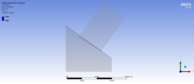
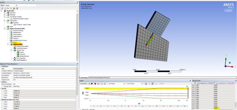
I am trying to analyse a model with 2 blocks. 1 block is inclined and 1 block is wedge shaped as shown in file attached. The bottom face of lower block is fixed and frictional contact is provided with co-efficient of friction 0.65.

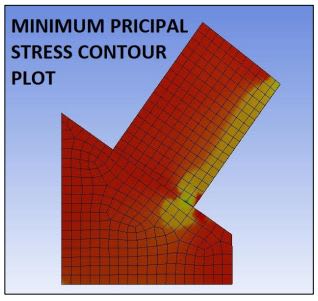
Joint is provided at inner edge of block and upper face of topmost block is loaded with inclined load as shown in file.

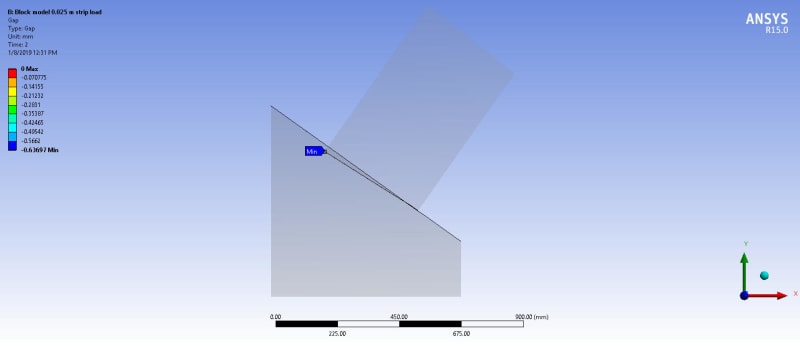
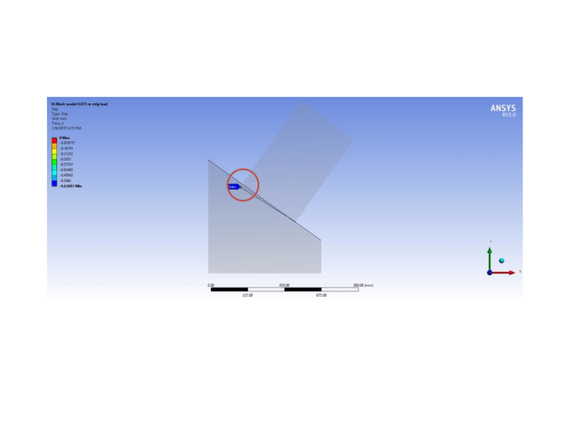
There is undesired penetration in the block. I want to neglect the penetration from the analysis.

Any help will be much grateful. Kindly help me with the problem.


Regards

Akshay Shelke

Structural Engineer
 
 https://files.engineering.com/getfile.aspx?folder=b10529ac-516f-4645-849b-49c8502ccdd7&file=PENETRATION_DUE_TO_JOINT.pdf
Replies continue below

Recommended for you

Increase contact stiffness, or change contact algorithm to Normal Lagrange or MPC - they don’t have penetration at all.
You can read about contact setting here Link
 
You can also plot the peneration by using contact tool. Directional deformation takes also into account
the possible deformation of the lower part.
 
Thanks for the reply @karachun. Increasing the contact stiffness reduces the value of penetration but the penetration at the outer edge is relatively the greater than the inner edge (where no penetration is there). I have tried to change the contact algorithm to normal Lagrange but the solution is not converged after solving few iterations. MPC formulation can't be used since Bonded or No separation contact doesn't justify the real life problem which I am trying to solve.
Again, thanks for the link you have provided I have gone with link and found that my contact settings are satisfying the information in the link.
The problem is still the same.
 
Thank you @L K. The bottom surface of upper trapezoidal block is contact surface while the slant face of the wedge shaped block is divided into 3 faces for creating joint edge (with the help of face split command). since there are 3 faces of wedge shaped block they are defined as target.
The results for penetration showing absolutely no values for the contact. Result for gap is showing -0.63 for the contact.
What should I derive from the results?
1.
PENETRATION_contact_tool_b8qnjn.jpg

2.
gap_contact_tool_g5iwli.jpg


Please check above result images for Penetration (1) and Gap (2).
 
Erik Sir, the deformation scale is 350 times the original deformation. Sir, the deformation value is not the problem but the effect that these values producing on the stress concentration and the stress distribution is the main issue. I am attaching the stress contour plot with this message. Kindly check the image at the edge where penetration occurs.
The crushing is expected rather than the penetration.
How can I attach the file? Should I archive the file or should I attach .wbpz formatted file?
 
In the highlighted region (red circle) in the image below, we can see that the top part going through, this is of course due to the fact that you are exaggerating deformations. The only meaningful scale in nonlinear analysis is 1. With that setting I would expect the top part not to go through of course.
pen_pk5dts.png


As for you second question, since you have sharp corners (on the opposite side also of the where I put the red circle) being pushed into the bottom part, and fixed at an edge also, that results in a stress singularity. If you want to capture stresses there you must put in fillets, and sort the joint restrain (not sure what it represents).

As for attaching files, there is a link, at the bottom when you reply to a thread, called Attachment, Click here to upload your file. Use that.
 
A couple of things.
0. Make sure your faces in contact are parallel, and bring them, so they touch, because it seems there is a large gap between them. Always best to let the contact faces be touching.

1. Split geometry )half symmetry), and apply symmetry BC on that symmetry face (prevent from sliding sideways), and to reduce run time

2. Remove joint (you might want to think what you are trying to represent there)

3. Add 10 steps

4. Ramp loads (force) gradually through these steps

5. put a support normal to the face of the top block on the side where the joint was in order to prevent from sliding down the wedge part. Remove/deactivate that support, say on the 3rd step. This support is to stabilise the top part, until frictional forces build up in order to prevent it from sliding down

6. You might need to increase stiffness of the contact to factor of 10 in order to prevent penetration

7. Look on both contact reactions and fixed support reaction making sure they are same magnitude as applied load

8. Use contact tool to analyse contact status, pressure,..
 
Thanks for Help Erik and sorry for delayed reply.
Starting as per the sequence of points suggested, I have tried to perform them on my model.
I have tried point number 1,2,3,4,6,7 and 8. I have done all those things you have mentioned in those points. But the penetration problem is still there.

Talking about point number zero "making contact faces parallel" and got your point and will try and let you know about the results.

Point number 5 is pretty good and I will perform the analysis with this solution and will let you know about the solution.

Once again Thanks for the help.

Regards
Akshay Shelke
 
I have done a small example similar to yours, and based on all the above points and it works fine. The applied force is 10000N, and as seen that is reacted OK by the contact.
wedgeblock_csyf7r.png


As for the surfaces to be parallel that is also important as it will make the contact much easier.
(I would make the wedge, and separately define a coordinate system that is aligned with the top wedge edge and on that edge (e.g., use make coordinate system from face and pick the wedge inclined face), when defining the top block, in that way they will be parallel, and touching.)
 
Thank you Erik for posting such a great reply.
I have also little query about the analysis you have performed. have you defined the Loads as shown in the file along with the question post?.
The question I have posted needs upper block to rotate from the edge I have provided the joint. I have checked the exact solutions you have provided earlier that is to make wedge block surface parallel to the block face and replacing joint with the support that will be deleted after few iterations.
The solution of support didn't worked out well but making surface parallel worked out well.
Although the solution I wanted is still not there. The block is not rotating at the joint edge.

For a little assistance can you please define a joint at the edge of block (where I have defined. And post the S3 plot for the same?

Thank you again.
 
You can try it if you want,but I do not have the time to test these things.

My recommendation is to actually represent what ever is there with a 3D model, and connect to the rest via bonded or frictional contacts (it is related to the point about thinking through this joint and what it represents)

Have in mind though that when the model wants to topple over and rotate a lot, the model will be unstable and it will not be able to solve so easily when that happens.
 
Status
Not open for further replies.
Back
Top