Continue to Site

Eng-Tips is the largest engineering community on the Internet

Intelligent Work Forums for Engineering Professionals

  • Congratulations KootK on being selected by the Eng-Tips community for having the most helpful posts in the forums last week. Way to Go!

How can I use reference dimension to drive a sketch dimension in the same sketch in NX10?

Status
Not open for further replies.

RC225

Mechanical
Oct 21, 2016
2
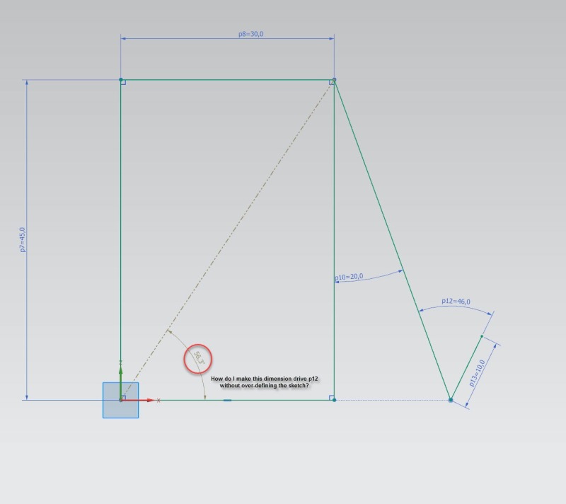
If I have part of a sketch that is fully defined by driving dimensions, how can I take a driven/reference dimension from that and use it to drive another dimension in the same sketch? It seems that as soon as I make a driving dimension a reference dimension, I lose the ability to use that value in an expression. I've attach an example sketch describing what I mean.
Reference_Dimension_Help_ozcfix.jpg


Being new to NX and coming from a SolidWorks background, I'm used to being able to do this and it really helps with visualizing how geometry changes with a given set of inputs.

Any help would be greatly appreciated!
 
Replies continue below

Recommended for you

That makes sense. Is there another way to do accomplish what I described? It would be sweet if I could store that measurement as an expression and use it wherever I'd like, but I can't seem to do that either.

Thanks for the response!
 
You could create a 'Measurement' expression outside of the sketch which would store the value of the angle. Of course, that value could NOT be used by any of the constraints inside the Sketch itself since it would come later in the history.

John R. Baker, P.E. (ret)
EX-Product 'Evangelist'
Irvine, CA
Siemens PLM:
UG/NX Museum:

The secret of life is not finding someone to live with
It's finding someone you can't live without
 
I agree that this seems like it should be -basic- functionality to use a reference dim in an expression elsewhere. You may not give a damn -what- that angle is, but WHATEVER it is, another feature may need to be in relation to it. This isn't uncommon, I find.

Regardless, if you want to use the angle in that reference dim you'll have to create a formula using something like the following, based off whatever 2 lengths you are driving with.
Code:
atangent(p10/p12)
or whatever numbers or function is necessary.

ETA: I can remember using reference dims in Autodesk Inventor back in 2003 or so, to drive other expressions. As well as in Solidworks a few years ago. As I just showed - it's not insurmountable, but it's a bunch of extra work that should be simpler.
 
Edit P12.

Where the value is, pulldown and pick Formula...

For the value enter the name of the angular dim (I'm guessing P9 from your graphic? use Expressions to figure out which is ~56.3 if you are not sure; mine was P7 as shown).

sketch-ref-dim_lkytxl.jpg


I tried it twice and worked finein both NX 9 and NX 11.

Hope that helps.
 
CADPat said:
I tried it twice and worked fine in both NX 9 and NX 11.

Until the sketch changes and you are left wondering why P9 didn't update.
When you convert a dimension to reference, the value is frozen and no longer updates unless and until it is converted back to a driving dimension.

www.nxjournaling.com
 
Thanks for the correction Cowski.

The matching of Ref Dims is the way we always did this in I-deas, which is why I tried it this way, and when it worked in Forward Create, I assumed the rest would be equivalent as well. My bad!

So you can jiggle the handle, by manually converting to Driving, then back to Reference, any time the Sketch updates, but not only is that a pain, but worse, you get a wrong result if you forgot to do that, so it's not worth it.

So I guess the previous suggestions to use TAN or unit triangle (maybe better, IMHO, in case the rectangle is not along horz/vert?) is your best bet for now.
 
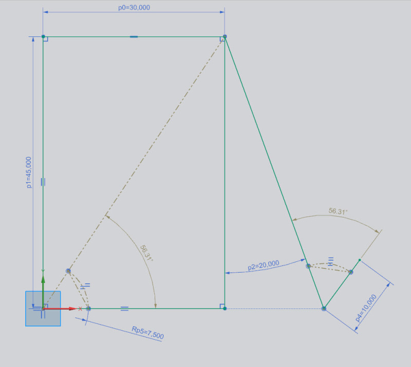
You could try this - I added and arc and a line coincident with the ends of the arc to both angles. The arcs are equal radii and the lines are equal length. Because this is enough to constrain the angle to the right, both angular dimensions are now reference. I changed the horizontal dimension and the angles both updated and their values were the same.

Will this work for you?

Ref_Dim_mkyxgt.jpg


Chris Cooper
Senior CAD Specialist
Cleveland Golf/Srixon
 
That's an interesting way to skin that cat. It'd not completely removed from "design intent" but it might make another viewer/user a bit confused. That's why I liked the method of making a formula. Anyone familiar with geometry/trigonometry should be able to read it and say "Oh, it was intended to always be parallel/equal to this chord/line/diagonal" which I always like. I want people to be able to know what the heck I was thinking when I constrained things the way I did.

It is also so very satisfying when I go to update things and everything 'upstream' goes exactly where it should go without touching it.
 
For this kind of problems I used two and more sketches... First one with basic dimensions, then next with measures from first implemented, and so on. It works very nice. It was way more complicated than this and I did not even try to put all in one sketch.

_____________________________
Enjoy your work and have fun!
 
Status
Not open for further replies.

Part and Inventory Search

Sponsor