Eng-Tips is the largest engineering community on the Internet

Intelligent Work Forums for Engineering Professionals

  • Congratulations waross on being selected by the Tek-Tips community for having the most helpful posts in the forums last week. Way to Go!

How do I calculate the frictional force resisting overturning on a banded pipe saddle?

Status
Not open for further replies.

Jazzy47

Structural
Feb 22, 2013
26
0
0
US
Hello,

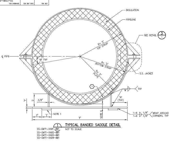
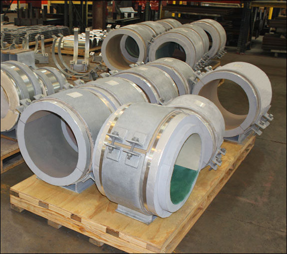
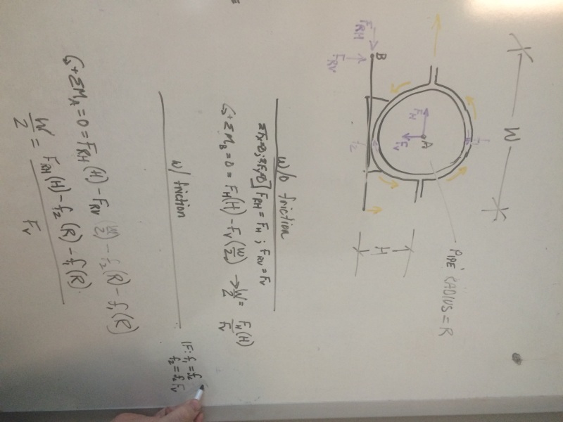
I was tasked to design a standardized guided banded pipe saddle. Our worst case simulation models from AutoPIPE are coming up with large ratios of horizontal to vertical loads, so we are investigating overturning as an issue. With the numbers we came up with, it seems to prevent the worst case overturning from all realistic client pipe classes/situations, we would have to use very wide base plates which are unrealistic for pipe spacing requirements. Now we are looking at how the friction of the saddle band against the pipe might help prevent overturning. Assuming the saddle would rotate around the very outer corner of the base plate, my project manager suggested using the equations/method below. I was wondering if this was an oversimplified approach. I realize frictional force is calculated by F=µN, however it is not a single point of contact and I feel there should be some kind of angular component or something involved. It seems from an internet search that the formulas for disk breaks etc. are more somplicated, and while it's a different problem it's still friction on metal stopping the rotation of metal. Am I over complicating this?

friction_wwihlj.jpg


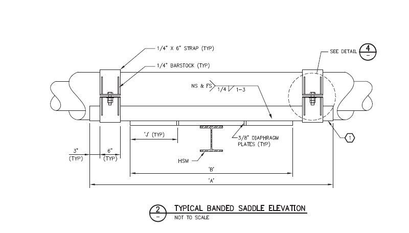
Here is a side view so that you can see how the bands attach. Thanks

side_view_l7j9ty.jpg
 
Replies continue below

Recommended for you

OK. So according to the drawing you have an insulated pipe sitting in a "semicircle" band (cradle?) held together with the bolted 1/4" bands and 1/4" barstock and some kind of plate welded to the underside of the band (cradle) that doesn't seem to guide anything.

Piping Design Central
 
The saddle assembly is allowed to slide on the HSM (support beam) and is just restrained laterally if it hits either of 2 stop plates at some gap distance on either side of the saddle/pipe.
 

Ah. It looked like those 3/8" "diaphragm plates" had something to do with being mis-drawn longitudinal stops on either side of the HSM. They still don't look correct as drawn.


Piping Design Central
 
Ah. No, I believe that is just for strength and rigidity of the saddle and does not extend down to interact with the beam. The pipe is free to move longitudinally, and the saddle is strapped to the pipe but not welded to the beam.
 
Here is a front view, if it helps. This is from the client's typical details, so we are just to use it as a general go-by but have some leeway. I was mostly just curious about the overturning friction from interacting with the bands. They are bolted on and can have variable tension on the pipe.

front_in2db0.jpg
 
It helps, but the elevation view and the new 'front view' detail still don't match. Sorry, I'm just a stickler for detail.

Piping Design Central
 
P.S. where the vertical plates are with the "G" dimension in the front view, I have also seen them use angles instead (running along the longitudinal direction supporting the curved plate).
 
OK, I've finally got this - Its a long saddle ( about 1/3 of a pipe in circumference with two external bands 6" wide clamping what I assume is an externally insulated pipe so the outer coating is PE or steel or ??

This pipe clearly moves about a bit and you're concern is that the horizontal forces will mean the pipe hits the side stops and then rotates.

If you think this is a concern, I can't see why your side stops don't just become an angle that the plate slide within which has a few mm clearance of the plate (say 5) so that at worst your plate will lift off one side, but only by a few mm.

normally you wouldn't really want your side stops to see much force, so if you're getting very high loads then you might need to re-think the anchors and expansion loops.

Remember - More details = better answers
Also: If you get a response it's polite to respond to it.
 
Yes, you got it. Sorry, I should have done a better job at explaining. It is a pipe with 3" of insulation on the outside and a cladding around that of galv. steel of 0.03". It would be hitting the stop plate and then rotating about the outer corner of the saddle base plate. We have brought up the idea of using angles or clips on the stops to halt rotation, however the client gave the impression this was not preferable (not sure if it was a constructability issue or what). They want a standardized saddle (not just project specific), so they are having us look at the worst case line class and loop that they would potentially use. This led to coming up with unacceptably wide base plates, so I was asked to see how the friction between the bands and the cladding would realistically contribute to mitigating rotation (conservatively). I'm just trying to see if the friction formula I posted initially from my colleague is oversimplifying the matter.

Thanks!
 
I think with the insulation on the pipe if there is any rotation the pipe will just rotate inside the insulation, you won't be able to stop that with the clamps on the outside of the insulation. You need to control the pipe movement with a few anchors and let everything else move around a little. Any large forces transmitted from pipe to the saddle or bands will just crush the insulation, you don't want that.
You did not mention if the line is very hot, or cold. Maybe you want spring loaded pipe hangers instead of just resting on the structure???

Regards
StoneCold
 
The line was assumed to go a worse case temperature range from -50 (it's in an arctic environment) to 220. I agree with you about altering the loops, however I would need to get the client to agree as I was told to make a standardized saddle assuming the worst case overturning loads from all of the loop designs they use in practice. In this case I was only asked to find the friction between the band and the pipe cladding. You do make a good point about the insulation rotating. However, I'm an EIT at the bottom of the totem pole here, and the friction is one of the things I was tasked with haha.
 
Even though the saddle is in contact with the steel pipe I would not trust the friction force to stop rotation of the pipe in the saddle since maintaining live clamping force between saddle and pipe is costly and not recommended. If you consider the temperature range that you are after it is not viable a good idea either. If you consider internal insulation it is worse.

If you really need to stop rotation you need to weld a short pipe on the main pipe and lock in the position on the saddle. This short pipe can also transfer longitudinal main pipe loads if you design that way too. The loading/stresses on the weld and/or location of acting lateral and/or longitudinal forces will determine the short pipe geometry.

Hope it helps.


Hi jazzy47

If I understand correctly you are concerned that the saddle itself will tip over rather like a tortoise rolling onto it back.

that being the case then if you take moments about one corner of the saddle to the centreline of where all the vertical mass acts ( which would be half of dimension F in this case) then compare that with the moment due to the horizontal force on the pipe at the pipe centerline at a vertical distance from the same saddle corner as before.
If the latter moment is greater than the first the saddle will tip over, if it isn't it's okay.
If I have misunderstood you're post then why not post another front view of the pipe and saddle and show where you think the forces are acting and that way there will be no doubts.

Regards desertfox
 
Hi bimr

Thanks for the picture it does help, so from my prospective Inwould think taking moments about one edge of the base as I described in my earlier post is applicable.

It appears the OP must have got an answer as the threads been quiet for a while now.


“Do not worry about your problems with mathematics, I assure you mine are far greater.” Albert Einstein
 
Status
Not open for further replies.
Back
Top