2JL
Mechanical
- Feb 16, 2015
- 50
Hello everyone
I think the question stated above said it all but a little backstory anyway:
We are about to provide to our customers interface drawing to depict maximum outline, mounting points and other specifications of our finish products. Until now the idea was to use a lot of reference dimensions and very few GD&T and hard dims for mounting points.
But since eventually, we will have to do a first article inspection as we ask to our suppliers to do. We want to make sure what is specified will match as closely as possible the reality of the finish product. And this is raising two issues:
- When we initially design the product, there was not a clear definition of the interface. We roughly imagine what will works for potential customers and from there design all the parts. Detailed drawings for each of these never took the interface as primary focus. Our main concern was to get functional and working end product. Now to defined the customer mountings points, the original datum used at the part level are not longer available at the product level. we have to use surfaces relatively well related for that purpose.
so the question is how do I work out the corresponding tolerances? I think a quick stack-up analysis could lead me to a close approximation but what about the other uncertainties related to deformation during assembly, handling, transportation...? Is there some rule of thumb I can use to bonify the value I will get from the stack up analysis?
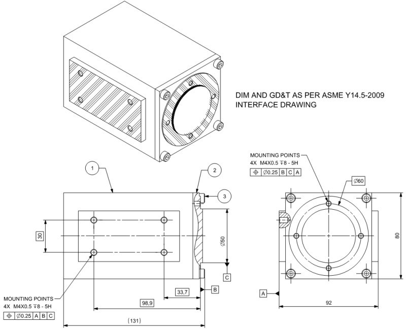
Refer to the attached sketch. Hatched surfaces are the functional surfaces available.

- How will the reference dimensions processed? will the inspection results considered always to be in-specs since by definition there is no criteria to decide otherwise? I found these two threads and it seems to lean towards using more hard dims and less reference dims (Link, Link).
Sorry for the long post and thanks for your suggestions.
2JL
I think the question stated above said it all but a little backstory anyway:
We are about to provide to our customers interface drawing to depict maximum outline, mounting points and other specifications of our finish products. Until now the idea was to use a lot of reference dimensions and very few GD&T and hard dims for mounting points.
But since eventually, we will have to do a first article inspection as we ask to our suppliers to do. We want to make sure what is specified will match as closely as possible the reality of the finish product. And this is raising two issues:
- When we initially design the product, there was not a clear definition of the interface. We roughly imagine what will works for potential customers and from there design all the parts. Detailed drawings for each of these never took the interface as primary focus. Our main concern was to get functional and working end product. Now to defined the customer mountings points, the original datum used at the part level are not longer available at the product level. we have to use surfaces relatively well related for that purpose.
so the question is how do I work out the corresponding tolerances? I think a quick stack-up analysis could lead me to a close approximation but what about the other uncertainties related to deformation during assembly, handling, transportation...? Is there some rule of thumb I can use to bonify the value I will get from the stack up analysis?
Refer to the attached sketch. Hatched surfaces are the functional surfaces available.

- How will the reference dimensions processed? will the inspection results considered always to be in-specs since by definition there is no criteria to decide otherwise? I found these two threads and it seems to lean towards using more hard dims and less reference dims (Link, Link).
Sorry for the long post and thanks for your suggestions.
2JL
