Continue to Site

Eng-Tips is the largest engineering community on the Internet

Intelligent Work Forums for Engineering Professionals

  • Congratulations GregLocock on being selected by the Eng-Tips community for having the most helpful posts in the forums last week. Way to Go!

How do you know how to calculate the flatness of a surface?

Status
Not open for further replies.

Baratheons

Aerospace
Feb 14, 2017
18
I passed the 2009 technologist test and I have a pretty good understanding of what each geometric characteristic means. But generally how do you guys know how to calculate the flatness of a surface that attaches to a mating part or rather what tolerance to put in the FCF? Anyone have good examples of practical applications, exercises that I can try out or read about. Everything in the standard is pretty theoretical.
 
Replies continue below

Recommended for you

I have mentioned this subject for maybe a decade and not gotten a single response indicating that any functional requirement beyond simple geometry is ever looked at. Ideally this limitation would be arrived at by a stress analysis, but there's little if anything on the subject.
 
Some tolerances such as position and perpendicularity are calculate-able, based on the formulas for virtual condition. (Of course, that requires that you have some other known inputs first.)

When it comes to flatness, there's no magic formula. The tolerance can be determined by lab studies, best guesses, looking at previous histories of similar parts, or simply talking to the manufacturer or customer.

John-Paul Belanger
Certified Sr. GD&T Professional
Geometric Learning Systems
 
The real requirement for flatness is typically, as 3DDave alluded to, based on stresses in the assembled condition.

If two machined parts are bolted together, flatness deviations cause bending loads in the parts as they are clamped together.

In the real world, where we use CNC machines and cold rolled stock for a lot of parts, flatness deviations are typically small enough that the induced stresses don't matter all that much. With the exception of a few specific situations (parts which require very high tolerances, gauging/optical tables, etc) the level of surface flatness produced by a squaring pass on a machine tool is well in excess of what is required to prevent parts from failing.
 
It all depends on the functional requirements of the parts. We have a lot of valve components that need to mate closely for good sealing. We specify 2 microns flatness across 3 common zones (legal in ISO). But it would be wasteful to spec that if you didn't need it. We have 35 years of experience behind that specification.

----------------------------------------

The Help for this program was created in Windows Help format, which depends on a feature that isn't included in this version of Windows.
 
Definitely from function.

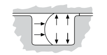
Say, the gap on this O-ring application cannot exceed certain value:
Capture_vqqxmd.png

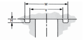
So when designing joint like this:
Capture_z2pi2r.png

you have to apply certain flatness to mating surfaces.

For your everyday garden-variety application the rule of thumb may be seeing your form tolerance as a refinement of size tolerance controlling the same surface:
60% of size tolerance - normal accuracy
40% of size tolerance - high accuracy
25% of size tolerance - extra high
Naturally, like dgallup mentioned, there may be years of experience behind certain tolerance values


"For every expert there is an equal and opposite expert"
Arthur C. Clarke Profiles of the future
 
Status
Not open for further replies.

Part and Inventory Search

Sponsor