Continue to Site

Eng-Tips is the largest engineering community on the Internet

Intelligent Work Forums for Engineering Professionals

  • Congratulations IDS on being selected by the Eng-Tips community for having the most helpful posts in the forums last week. Way to Go!

how Full is Liquid piping 1

Status
Not open for further replies.

RanjanC

Chemical
Sep 21, 2015
3
We have a scheme where Lean Amine Pump discharges to a high pressure Amine Contactor. There is dual check valve near the amine inlet to column to prevent high pressure gas back flow to amine circuit in case of lean amine pump trip. In the HAZOP analysis, a scenario came where the lean amine stops and check valve leaks to pressurise 150# rating suction of Lean amine pump. It may be noted that lean amine pump has a booster pump with its check valve. What we thought that any small leakage of amine from the Amine column upstream of dual check valve can pressurise the upstream amine section if it is 100% liquid full.
My questions
a) Is liquid pipe in pump discharge always 100% full of liquid?
b) Can any voidage be assumed for liquid fill pipe to accept back pressure of additional amine pushed through the dual check valves by high pressure gas?

Thanks
RC
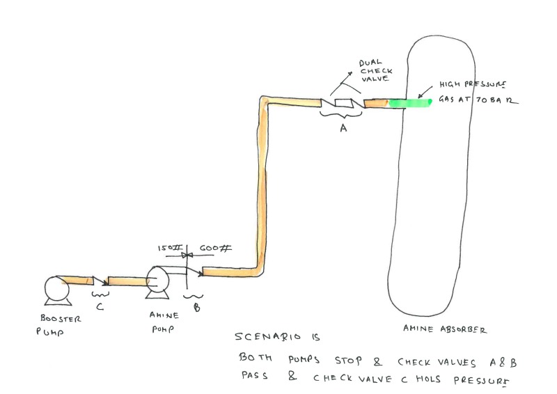
Sketch_rgvrvw.jpg
 
Replies continue below

Recommended for you

Simultaneous failure of two pumps and three check valves is a scenario, having extremely remote probability to occur. It should not be more than level III or IV risk category when you plot on Severity-Likelihood graph. The scenario may carry a high severity but its extremely low likelihood brings the risk at a fairly low level. According to Process Safety Risk Management (PSRM) protocol, level III and IV risks are not considered for an immediate action because such work will be "good to have" only. In my opinion, installed hardware is adequate.

To answer your question,

1. Yes, discharge side pipe of a pump is always 100% full of liquid
2.In case of a sudden loss of flow due to pump tripping, vertical portion of the pipe will remain full of liquid without any "voids"

 
I think there is an error in your sketch - piping specification break cannot be on discharge of the amine pump, but on the suction side. On the discharge you already have higher (amine contactor) pressure system.

1) For all vertical piping (and all piping sections upstream of the vertical section) you can safely assume that the line is liquid full. It would not be possible to move the liquid vertically in a partially filled system. It is hard even to visualize such phenomenon.
2) Do not assume any void for liquid full system. There is no basis for such assumption.

With two (dissimilar?) check valves one can take credits for leakage or back-flow equal to 10% of the flow calculated based on assumption that 10% of the check valve cross-sectional area is available for reverse flow. So the scenario here could be:
- gas leaks back to the amine supply line;
- gas pressurizes the amine supply line and pushes the amine back towards (and possibly through) the amine charge pump;
- liquid pressurizes the suction side of the amine charge pump;
- consequences would be reverse rotation of the charge pump and overpressure of the suction line above 150# conditions.

PSV on the suction side of the charge pump seems required.

Dejan IVANOVIC
Process Engineer, MSChE
 
Thanks Gents for your analysis!
Agree that this is high severity of consequence but low likelihood scenario. I realised that the spec break should have been in the suction of lean amine pump.
There is no provision for PSV on suction of the pump. But the Amine Regenerator Column from which the first pump takes suction has got PSVs.
Now that I know there is no liquid space available for any liquid pushed by the first set of check valves; will it help to drill holes in the flapper of check valve C so that any leakage is passed on to upstream sink which has got lot of volume?
 
I am not sure about the operating conditions but the pressure ratings seem to be a bit disturbing if we assume the flow from the pumps to the vessel. Don't you think the second pump pressure should be same as the discharge line or higher?
 
If you drill holes in the NRV flapper, the valve is no more a non-return valve and it has lost its purpose (design intent). This will likely open a whole new set of potentially hazardous scenarios and operability/maintenance issues.

I think you will need a thermal relief valve between the two pumps in any case so why not make sure there is a PSV instead, that can handle pressurization for the reverse flow case?

Dejan IVANOVIC
Process Engineer, MSChE
 
If you're accepting that flow might be able to go backwards into the upstream system, you're better off with a regulated pressure relief valve on the #150 line discharging back into the upstream system. To me this is much better and maintainable system than a hole in a check valve. The problem with a hole is that it can either block or if the leakage rate past your U/S valves exceeds a certain flow, the u/s pressure can be quickly more than your #150 system.

I've never liked trusting check valves where there is a big discrepancy between class ratings such as this. 70 bar on an #150 system could very easily cause rupture and I would normally suggest a FC isolation valve linked to a pressure switch and auto closure on pump stop.

The relief valve back to U/s would help a lot though, IMHO.

Remember - More details = better answers
Also: If you get a response it's polite to respond to it.
 
Thanks Gents for your insights!
I should have clarified:
a) This is a constructed plant
b) No new design modifications like installing PSV look appealing at this moment
c) The check valves at the inlet of the Column are so called high integrity dissimilar valves
And last but not the least
d) there is a Shut Down Valve linked to pump stop/low pump discharge pressure/low pressure differential across the Dual check valves. But the valve takes 45 sec to close.

In summary we are looking for a pressure relief scenario for a very momentary scenario when pumps trip and the shut down valve is closing and high pressure gas is pushing amine through the check valves. Given the very low likelihood and as built nature of the plant; I was scampering for solutions like
a) any voidage in liquid piping (ruled out)
b) any voidage created due to density difference of amine at different pressure (no noticeable change in density)
c) Drill a hole through the first Check valve so that it acts as a pressure/thermal relief minute alternative

Regards
 
You can also look at the option to close the SDV valve faster (i.e. use air exhaust booster etc.) as 45 seconds seems quite a long time.
Also, if the calculated process safety time (PST) between the pump trip and over-pressurization of the 150# piping is less than 45 seconds, no further safeguard actions would be required.


Dejan IVANOVIC
Process Engineer, MSChE
 
How about a pressure accumulator on the class 150 section that would accept a certain volume without raising pressure above the #150 limit within your 45 seconds.

That isolation valve makes all the difference. Not sure how it manages to take 45 seconds to close, but there's another option - speed it up a bit?

Remember - More details = better answers
Also: If you get a response it's polite to respond to it.
 
RanjanC,

Note that 150# class flange rating under 100 deg C is maximum 20 bar to ASME B16.5. Therefore the second pump is not able to push the liquid to the vessel which is under 70 bar. You either have very low operating conditions or your second pump rating is wrong. Check one of the options under the following google search:

 
Dejan,
I don't think the available leakage in your first post really makes sense. I use 10% for the first check and 10% of 10% (i.e., i%) for the second if it is the same technology and 0.5% for the second if it is different technology. For the third I use 5% of 0.5% (or 1%) or basically zero. Using 10% of total pump capacity seems to be way too conservative.

RanjanC,
If you look at the leakage back to the pump then with the credit for three check valves, if the pumps are centrifugal as drawn then what gets through the third check (which is probably the actual spec break) can easily get through the pump to the existing low pressure accumulator.

I wouldn't change a thing in this design. I absolutely would not drill the checks. I see this design all over the world and it works great. Adding PSV, surge bottles, interstage accumulators, etc. simply adds complexity without adding any increased process safety.

David Simpson, PE
MuleShoe Engineering

In questions of science, the authority of a thousand is not worth the humble reasoning of a single individual. Galileo Galilei, Italian Physicist
 
Hi Dave,

The sentence (and philosophy) I quoted is from API 521 Pressure-relieving and Depressuring Systems" 6th Edition (2014): "Where multiple check valves in series are inspected and maintained, assume the smallest check valve has completely failed and all other inspected and maintained check valves have severe leakage. Because of potential common mode failures the user is cautioned against taking a larger credit for more than two check valves in series that are inspected and maintained."

Now for the reverse flow calculations there are several options proposed within the same standard, but the most common used in HAZOPs is actually based on 10% of NRV diameter (not 10% of X-area, I apologize for incorrect quotation in my first post) which still yields significant leakage rate. Ultimately it is up to the end user to evaluate and estimate the magnitude of reverse flow.

Please note that the issue with this particular scenario (and many others) is that it is very unlikely for such event to happen. If observed purely from the consequence perspective, the required level of protection would be very high. Once when the likelihood and the available/existing safeguards come into equation, it could easily happen that the overall risk (not the consequence) is acceptable and falls within ALARP area. This varies from case to case, and from each plant the overall risk of the same event could be (and is) in very different categories. That is why it is always good to perform evaluation for each plant - generalized perception might be deceiving.


Dejan IVANOVIC
Process Engineer, MSChE
 
Dejan,
In your current job you are way more current on the code than I've been in the last decade. I don't agree with the code, but the code is the code.

There are several comments above about the consequence of sending absorber pressure back to the accumulator. The actual consequence is approximately zero since the LP piping is assumed to be protected by the PSV on the LP accumulator in this case. If the booster pump is a PD piston pump (very rare), then I'd be concerned about the section of LP pipe between the check and the pump outlet, but with any kind of dynamic pump the volume sink in the accumulator is more than adequate for the absorber to completely depressurize without overpressurizing the accumulator faster than the PSV can handle.

David Simpson, PE
MuleShoe Engineering

In questions of science, the authority of a thousand is not worth the humble reasoning of a single individual. Galileo Galilei, Italian Physicist
 
Status
Not open for further replies.

Part and Inventory Search

Sponsor