Continue to Site

Eng-Tips is the largest engineering community on the Internet

Intelligent Work Forums for Engineering Professionals

  • Congratulations SSS148 on being selected by the Eng-Tips community for having the most helpful posts in the forums last week. Way to Go!

How much tension ? 1

Status
Not open for further replies.

xtal01

Mechanical
Mar 15, 2012
143
OK ... I have a friend who is about to try raising a wall ... his idea worries me (a lot).

He figures he will more or less build half a scissor jack.

I looked at his idea and I think the tension in the member that brings it together will be amazingly high.

I am a machinist and don't know how to calculate the tension in the lifting member.

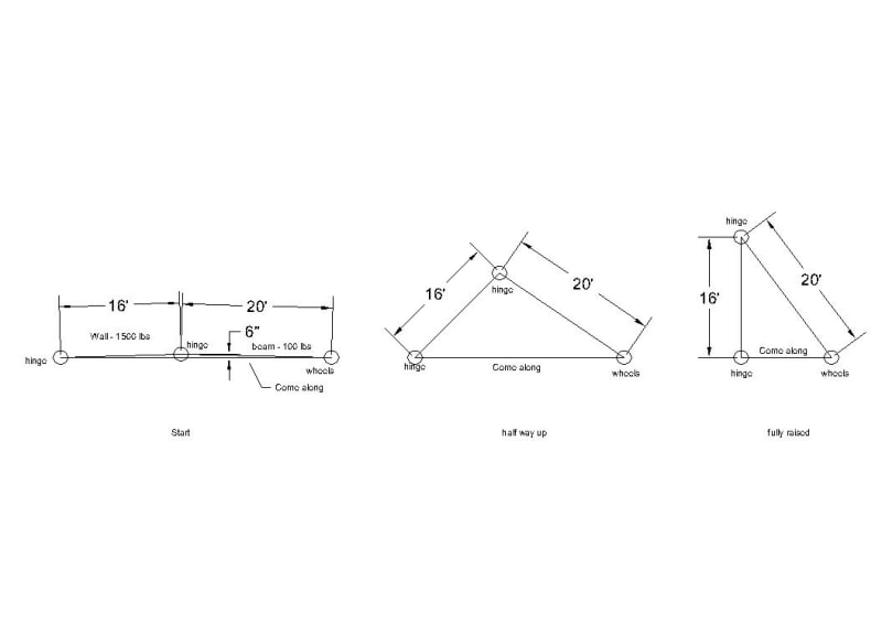
I tried to draw it. He has a 16 ft wall section ... about 1500 lbs.

One end is hinged.

He wants to put a beam hinged at the top of the all and a come along between the bottom of the wall and the bottom of the beam.

The bottom of the beam will have wheels.

We know the most tension (force) will be when he wall is almost flat. He will lift the wall a few inches just to get it started.

I was not sure if this all makes sense for I drew it with the wall in three positions .. just starting ... half way up .. up.

Can you tell me how much force will be needed to lift the wall? He is thinking of using a 2000 lb come along. I don't know if it would be enough.

Thanks .... Mike
raise_wall_wwhf1q.jpg
 
Replies continue below

Recommended for you

Your intuition is correct.

At such a flat starting angle (1.8o) the tension will be approx 14,200 lb.f (assuming I have not screwed up my calcs).

It would not be until a lift angle (panel to horizontal) of 12.5o [EDIT: about 3.5 ft off the ground] before tension in the come-along will be reduced to 2,000 lb.f

Your friend needs to also consider stability upon reaching the vertical alignment in that panel does not fall backwards, and also during the lift as the wheels on the RHS will need uplift restraint (i.e place them in a screwed-down channel track etc).

Also need to look how the assembly is stable for any out-of-plane actions.
 
Awesome!

I am not an engineer but if it doesn't look right I "usually" stop and do some homework first ....

I have watched a lot of interesting things in my life ... one neighbor lost a finger in a snow blower ... the other part of his hand clearing a lawn mower ... the other fell when the ladder slid in the truck (it was too short so he put it in the truck to get a few more feet of height) ....

I could just imagine this going wrong ...

Thanks!


Well in this instance he simply won't be able to get it off the ground so will be internetwork safe.

Still struggling to work out what a hinged wall is doing....

Remember - More details = better answers
Also: If you get a response it's polite to respond to it.
 
No chance. The come along won’t lift it.

Even if strong enough I’d still be very concerned about connections, stability, etc.

You need some sort of hoist. You could make one.
 
Thanks ...

I think I found a solution for him ...

I have another friend who owns a telehandler

I put the two in touch so I think he can borrow it to get the wall up.

Just FYI .... the hinges were just to stop the wall from kicking out at the bottom .. will be removed when the wall is up.

Thanks again!
 
Xtal01:
Have your friend look at Wall Jacks, specifically made for the purpose of tilting wood framed walls up, after being built on the floor deck. They are about $1500 a pair, and can probably be rented in some places. The walls are usually sheathed on the deck so they do not rack or parallelogram during the lifting process, they must be braced in some way for lifting. Five or six guys can usually lift/tilt these walls up in unisone. The hinging can be as simple as some heavy duty strapping from a lift of framing lumber, maybe some scrap Simpson coil strapping. Assuming a 2x6 stud wall…, The bottom of the sill pl. is positioned on a snapped line 5.5” or 6” in on the deck from the final line position of the 2x6 sill pl./stud wall outer surface/plane or the .5” sheathing outer surface/plane. The strapping is nailed to the deck and extends 5.5” plus outboard of the snapped line. The strapping is bent up on the bottom of the sill pl. (maybe bent again over the outer/top edge of the sill pl.) and nailed to it. The sill pl. stands up, on edge, and is toenailed to the deck. These toenails will bend and pull out during the lifting process, and can then be cut off. Draw a section through this detail and you’ll see how I t works. The wall must then be kicked into final position, plumbed and braced in the vert. position. Many of the wall jacks have some sort of hook at the top which tends to prevent the wall from going too far.
 
Status
Not open for further replies.

Part and Inventory Search

Sponsor