Eng-Tips is the largest engineering community on the Internet

Intelligent Work Forums for Engineering Professionals

  • Congratulations waross on being selected by the Tek-Tips community for having the most helpful posts in the forums last week. Way to Go!

How shallow an angle of V would still align with a round metal bar? 3

Status
Not open for further replies.

ship69

Mechanical
Nov 23, 2015
22
0
0
GB
Hello

I am new. I have simple a mechanical design problem:

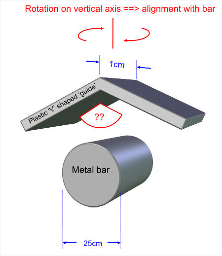
1. I have a cylinder - i.e. a round bar - that is 25mm in diameter and made of polished metal (chrome).

2. I have an inverted V shaped guide made from smooth plastic (probably polyethyline PE or similar. This inverted V will be fairly short - only 10mm (1cm) deep.

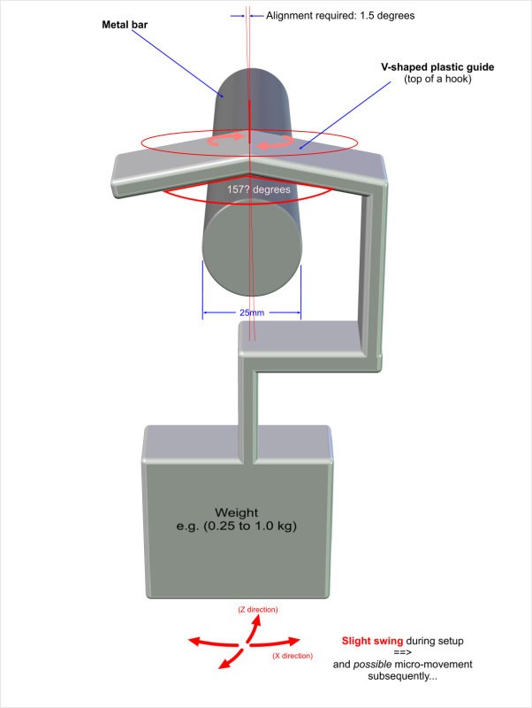
Now, the plastic inverted V shaped guide will be resting (unsupported) on top of the round bar, with a light force equivalent to say 200 grams, and it will be able to twist along a vertical axis.

My question is this:
How shallow can I allow the angle of inverted 'V' to be and still expect the V to rotate so as to align with the direction of the metal bar? i.e. to point in the same direction. (The alignment of the two objects only needs to be within a few degrees)

To explain:
If the V is extremely steep say 45 degrees - or even 90 degrees - then it would be reasonable to expect the V to align EXACTLY with the bar. But if the V is very shallow and starts to approach 180 degrees, then one would not expect the V to rotate at all.

Are there any rules of thumb or guestimates that I could use?

J

P.S. Please excuse the very crude nature of the attached diagram, but I hope it brings the problem to life...

delme-guide02_ozu5xo.jpg
 
Replies continue below

Recommended for you

OK let me try and get my head around this.

1. Shallow 'compass bearing' angles
In the starting condition, if the top of the hook - i.e. the plastic (inverted) V - has been rotated horizontally to be aligned at a pretty extreme compass bearing (e.g. say 20 degrees) away from that of horizontal bar - then, given a reasonably steep V and a fairly low amount of friction between the plastic V against the metal bar then my assumption is that the V will definitely rotate towards a better alignment with the bar.

However the problem starts when the compass bearing between the V and the bar is more shallow, being as the corrective angles will be much more shallow.

2. Tighter alignment needed
I've run my geometry again and the bad news is that I need much tighter alignment than I had previously thought. Ideally as little as +/- 2 degrees would start to become a problem. So I am really looking the plastic V to come to rest at +/- 1.5 degree from the compass bearing of the bar.


3. Hydtools's calculations
I'm not quite sure what went into the 157.4 degrees calculation (it's is a pretty wide looking V either way). Is it the steepness of slop at which a down which an object (in simple terms think 'toboggan'!) would start to slide?

If so maybe we could find a way to use that. However the complication is that we need to get this angle calculated correctly - and this is NOT straightforward. Not least because the closer to true alignment of metal bar and V-shaped plastic, the smaller this angle will be. (This will be due to the fact that the plastic can only rotate around a vertical axis due to the weight at the bottom of the hook [although see Real World Experiments below, talking about swing.)

4. A possible simplification
One thing that might help is if we were to assume that the thickness/depth of the V was extremely narrow (approaching infinity - but still deep enough to have significant friction). Any increase in depth (Z direction) will help correct, so if something can work at a very thin (e.g. 1mm) Z depth, then it should work with my actual model.

5. Real world experiments ==> swinging
I have done some simple tests with a crude prototype and during the time when the weighted hook (containing the plastic V) has first been put on the metal bar, depending on exactly how crudely it has been hooked onto the metal bar, despite the fact that there is quite a lot of dampening by air, it will swing always back and forth a number of times. With fairly smooth surfaces this can easy be as many as 12 swings in the Y direction (see diagram). The air dampening in the Z direction is greater but that can swing a number of times too.

What I have only now released is that whilst any of this swinging is still happening, because things are already moving small corrections to the alignment become possible that would not have happened during static conditions.

[In hind-sight this is quite obvious - it's just that I hadn't realized how many swings would happen when the hook is weighted.


Here is a slightly improved diagram:

delme-plastic-hook-v03b_tpxrvm.jpg


With thanks

OP
 
Extremely narrow z, approaching zero, not infinity but knife edge, there will be infinite z swinging neglecting air damping friction. Increasing z dimension will increase resistance to z swinging.
Decreasing included angle will increase aligning force. X swinging will be damped by sliding friction.

What are your post-hanging motion requirements? Something more than just aligning the V to the bar?

Observe clothes hanger motion for clues.

Ted
 
> What are your post-hanging motion requirements?
> Something more than just aligning the V to the bar?
If the hook gets brushed lightly e.g. by hand, it would need to swing about a bit but again come to rest hanging (to within c.1.5 degrees) parallel to the horizontal bar.


> Observe clothes hanger motion for clues.
Yes - good call. The behaviour of the device will be pretty similar to that of a cloths hanger - with clothes on it.


P.S. CORRECTION: The diameter of the metal bar is 25mm (not 25cm) - my apologies.
I have corrected that previous diagram.


Ship69:
Wow! 25cm changes to 22mm, not much difference there. That certainly changes the proportions of the sketch and some of the considerations of the problem. The last few posts are really starting to get to the root of the problem. It seem to me that an improvement in the design would be, instead of the Vee shape at the apex, could you form that plastic top piece to match the o.d. of the rod. Then, if the included angle of actual contact was 10 or 15̊ on either side of the top of the rod (from 11 to 1 o’clock), it would have some real holding power and centering ability in each direction. RE: the coat hanger analogy, note also that while the head of the hanger doesn’t normally contact the rod except over a short length at the top of the rod, it does circle the rod from 9 o’clock to 4 o’clock, in terms of preventing falling off the rod. This would also allow you to significantly reduce the size of the cranks (lateral length dimensions, x direction) in the vert. portion of the hanger. And they could be nicer curved shapes (more generous curved shaped), rather than the 90̊, tight bends, which are very high stress regions. You would have better centering ability of the load, if the vert. length of the hanger was longer below the rod, if this is possible. What are you actually hanging from these hangers and how are they used. I find it hard to imagine that they might not see greater lateral loads than you suggest. How are they installed and removed from the rod? What is the area of the hanging article, as a sail to a slight wind? Can they be bumped?
 
dhengr:
Humble apologies again for my order of magnitude typo.

Exact diameter is not under my control. If the diameter of the horizontal bar was known like would be easier(!)

However in practice, depending on exactly where the the product that I am designing will be used, it will need to hook onto a fairly wide range of sizes of horizontal bar. This could be anywhere between 45 and 10mm, although more normally the diameter will be somewhere between 15mm and 30mm.

Btw, please ignore other issues such as aesthetics and stress levels at angled joints. (I have already dramatically simplified the over-all actual design in order to focus the issues I have raised. Moreover I am constrained by IP issues so can't disclose the actual design here.)

The product is for indoor use. Yes, lateral loads may be temporarily be larger that I suggest, in which case too bad - the product will move out of position. However the whole point of this discussion is to design something with a sporting chance of getting back into the 'correct' position when it stops swinging. :)


The gizmo is not so complicated that it couldn't be prototyped. There is something to be said for walking out to the shop and getting somebody to make you one, or get one 3-d printed, or cobble one together in your garage.
 
It might be better to make two separate Vs, each of short length, as a continuous V of similar length might not be straight and can rock. The discontinuous V will have 2 pairs of contact points, while the continuous one will ideally form two lines of contact. Any irregularity along either of the lines will reduce the V to two points of contact, spoiling the control.
 
3DDave said:
It might be better to make two separate Vs, each of short length, as a continuous V of similar length might not be straight and can rock. The discontinuous V will have 2 pairs of contact points, while the continuous one will ideally form two lines of contact. Any irregularity along either of the lines will reduce the V to two points of contact, spoiling the control.
This sounds intriguing. I don't quite understand. Do you mean one V inside the other (i.e. of shorter length) or one V behind the other? (i.e. further away from the viewer in my above diagram)

OP

 
Let's get the geometry sorted out first, and see where this leads us.[ ] Assume (as everyone has, perhaps heroically, been assuming) that both parts are infinitely rigid.[ ] Consider the geometry when the vee (whose included half-angle is alpha and whose "axial" length is L) is rotated by an angle beta relative to the bar (whose radius is R).

See my attached diagram for this situation.[ ] (Unfortunately I do not know how to include the diagram in the body of my post, for which my apologies.)[ ] It is simple trigonometry to calculate the height of the vee's ridge above the bar's centroidal axis.[ ] This height (H) is the sum of the two components H[sub]1[/sub] and H[sub]2[/sub] shown on the diagram.

Now, for the moment, assume that everything is friction-free.[ ] Under the action of gravity on its self-weight (W), the vee will want to slip back to its beta=zero position.[ ] To prevent this from happening we need to apply a torque to the vee, a torque T[sub]g[/sub] about the vertical axis.[ ] Using energy-conservation or virtual-work principles it is easy to show that the magnitude of this torque needs to be
T[sub]g[/sub] = W * d/db(H)
where d/db(H) is the first derivative of H with respect to beta.

I believe, but cannot readily verify mathematically, that this torque is smallest when beta is vanishingly close to zero.[ ] Under these circumstances d/db(H) can be shown* to be
d/db(H) = L/(2*tan(alpha))
and so
T[sub]g[/sub] = WL/(2*tan(alpha))
(*Being lazy, I did the calculus using the venerable Derive computer algebra program.)

Another result that comes from simple statics is that vertical equilibrium requires that the (radially directed) normal contact force between the vee and the bar be given by
N = W / (2*sin(alpha*cos(beta)))
at each of the two contact points.

Now think about friction.[ ] The key question is whether the friction is capable of generating a resisting torque that is equal to the gravity-induced restoring torque T[sub]g[/sub] (perhaps throwing in a factor of safety for good measure).[ ] The maximum possible friction force at each of the contact points is u*N where u is the coefficient of friction and N is as given above.[ ] This will be oriented directly opposite to the direction of the relative movement, but the direction of relative movement is not easily calculated.[ ] Assume, probably slightly conservatively, that the direction is the one that leads to the maximum resisting torque.[ ] The frictional resisting torque will then be given by
T[sub]f[/sub] = (u*N) * (distance between contact points)
[ ][ ][ ]= (u*N) * ( L/cos(beta) + 2*R*tan(beta)*cos(alpha*cos(beta)) )
For our case of interest, the case where beta is vanishingly small, this simplifies to
T[sub]f[/sub] = uWL/(2*sin(alpha))

If the calculated value of T[sub]g[/sub] exceeds that of T[sub]f[/sub] by a sufficient margin, then we can be confident that the vee will correctly self-orient itself on the bar.

 
 http://files.engineering.com/getfile.aspx?folder=1330ee8a-1028-4922-89fe-574594fc5b19&file=AngleStraddlingPipe.pdf
Denial's image:
AngleStraddlingPipe_a0uouc.gif

Fwiw, I couldn't get the PDF to work and so converted to GIF format.

I shall now be away - back in a few days.

OP
 
There is an error in my diagram.[ ] The hand-written expression for H[sub]1[/sub] should be
L*sin(beta) / (2*tan(alpha*cos(beta)))

This problem applies only to the diagram, and results from a careless transcription error when I created the higher quality diagram from the crude scratchings I had used when doing my algebraic manipulations.[ ] The algebra in the text of my above post is unaffected by this error.
 
One thing that needs to be answered is whether the alignment chevron needs to operate on the full diameter, i.e., if the portion of the cylinder that contacts the chevron had half the diameter, the chevron would be correspondingly smaller. Relatively small groove and pad kinematic mounts can be accurate to better than a few microradians.

One issue that you might consider is that if there is a lot of relative movement and dragging, the long term surface wear might be an issue. A plastic against steel will lose material over time.

TTFN
I can do absolutely anything. I'm an expert!
homework forum: //faq731-376 forum1529
 
The simplicity and familiarity of the above solution got me thinking I might have overcomplicated things.[ ] I had.[ ] Enormously.[ ] If we tip the problem upside down it can be reduced almost to a classic text book case that any high school physics student could solve.[ ] See attached diagram.

The critical value for alpha, the value at which the bar is just at the point of sliding along the vee (or, un-inverting, the vee is just at the point of sliding down the bar) can readily be seen to be given by
alpha[sub]crit[/sub] = arctan(1/u)
where u is the coefficient of friction.[ ] For values of alpha greater than this critical value sliding will not occur.
 
 http://files.engineering.com/getfile.aspx?folder=fad20c16-634c-4297-a2ef-d2d3093c0b44&file=Inverted.pdf
Yair, Hydtools, you got there directly.[ ] And week earlier.[ ] I took a (very) long way around, unable to see past what I took to be a complicated geometry.[ ] But I had a bit of fun along the way.
 
Status
Not open for further replies.
Back
Top