Eng-Tips is the largest engineering community on the Internet

Intelligent Work Forums for Engineering Professionals

How to calculate restoring forces/reactions for statically indeterminate linkage

Status
Not open for further replies.

Rohan K

Mechanical
Oct 8, 2023
3
0
0
IN
Hi members,
Rohan here and I am a Mechanical Engineer. Recently encountered a situation with a mechanism which could be compared conceptually to seemingly simple linkage where restoring forces for equilibrium need to be calculated.
But after trying to solve for the unknown forces I found that the no.of equations for equilibrium do not suffice to evaluate the no.of unknown forces/reactions keeping the link in static equilibrium.
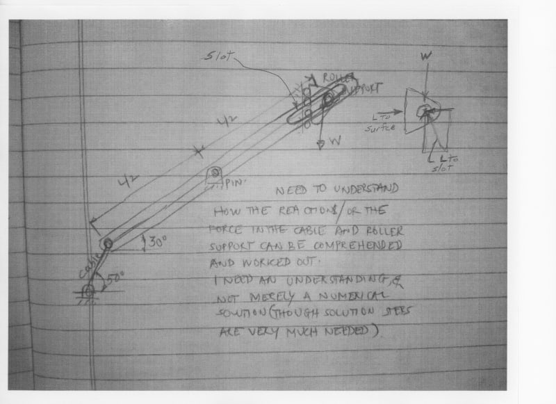
I need to understand the concept behind the approach to the solution to such cases where unknown forces outnumber the available equations and seemingly make the problem statically indeterminate (correct me if I'm wrongly interpreting this after seeing the attached figure).
Kindly help me understanding the concept behind this (any explanation from anyone/reference book with such cases/book/etc.) is more than welcome and if someone can shed some light on the F.B.D. of the case and steps hinting to equations/solution is needed and highly regarded.
The figure indicating the case is attached for your reference.

Thanks and regards,

Rohan


 https://files.engineering.com/getfile.aspx?folder=628cb5ff-c320-453c-833e-b4bf91850d15&file=Linkage_Image.jpg
Replies continue below

Recommended for you

Hi Rohan K

I assume that the link can pivot around the pin, if that’s so then it’s a seesaw and the rollers won’t sit squarely on the flat face.

“Do not worry about your problems with mathematics, I assure you mine are far greater.” Albert Einstein
 
does it pivot about the middle support ?

at a different angle (of the link) does the cable angle change?
but that would change the RH position from the middle ??

The reaction at the LH ground is determined by the cable (it's angle).
The reaction at the middle balances the load.

I don't think the RH (wall) has a horizontal load ?

"Hoffen wir mal, dass alles gut geht !"
General Paulus, Nov 1942, outside Stalingrad after the launch of Operation Uranus.
 
There is more to the problem than stated - setting the condition that the load on the rollers was zero would be one of them.
 
The system is structurally indetermined and it is not a mechanism either.

The cable connection makes everything more complex. Eventough the cable may be replaced by another linkage, it is the same unless it has a moment connection on unlinked side (rotating motion). However this may cause the rolling end split from supporting face during rotation at some angle range.

So IMHO this is not a good system to solve or design.

Perhaps you need to apply a horizontal force to the rolled end of pivot linkage at all time to keep it structurally stable. In this case why do you use cable connection than?
 
I thought the link was a three force member. if the RH load is vetical, and we know the direction of the cable reaction, then we know the direction, and magnitude, of the mid reaction.

I think you should start with easier examples, if you're just learning this material.

"Hoffen wir mal, dass alles gut geht !"
General Paulus, Nov 1942, outside Stalingrad after the launch of Operation Uranus.
 
Hi everyone, thanks for responding.

the idea is that the link is held in the given position (at the angle made by link and the cable/the cable can be replaced by a link too, with the horizontal)and the roller support at the right, leading to a static equilibrium of the link.
We could also replace the RHS roller support by a hinge pin joint , I think this would make it more familiar kind of a support. I tried doing this but the crux of the matter is that the no. of unknown forces arising do not get solved for by the usual three equations of equilibrium.
How to go about this.
We all can imagine that for a given (preconceived)angle of the link and cable/holding link and the RHS support (consider it as a hinge now instead of roller) would certainly keep the linkage in equilibrium. But how to determine the reactions at the RHS hinge, the center hinge and the LHS cable/replaced by a link.
As stated by me in the O.P. I just get going in rounds with the unknowns and available equations.
Kindly shed some light on how to systematically solve for the unknown reactions.
Any material where such indeterminate cases are explained with a solution in terms of equations, etc. is much required.

BTW, this linkage is a reduced to version/replication/conversion of a certain linkage in question (which arose in my mind). That equipment is in vast use worldwide and has a very similar linkage condition. So obviously it must have been worked out - if yes then how.

Please help me decipher this.
 
@ 3DDave
Its a two tiered scissors lift platform.

One of the two cross links of the top tier of the scissors lift platform is hinged at its upper end to the under of the top platform/table (and the second cross link of the same tier has a roller or wheel or bearing attached to its upper end and running under the top platform in a slot). These two cross links is pinned in the center (this pin joint connects the two cross legs/links of each tier)and then at the bottom end the link is pinned to the link/leg of the 2nd tier (lower tier).

this is the arrangement I'm trying to solve.

Now I think its clear to what I'm trying to ask and draw a similarity/reduce to between the sketch I attached and the real mechanism in question.

Now, if the top end of the topmost tier leg is hinged under the top table (at this point the load is transferred to the scissor lift links)and this end is hinged as mentioned earlier, I was trying to solve for all the unknowns.

People I have seen (I referred to dozens of technical papers) treat the top end to be free and only to carry the load from the top platform vertically downwards. In this assumption its all easy to calculate the forces.

But the reality is that the top end of the link is hinged connection under the top table and not free.

How to then solve the linkage (that's what I have tried to best replicate in the sketch - and I'm sure I didn't make a mistake in depicting it to the best similarity)

Now can someone help me out with this to find all the reactions ( 1. at the hinged joint at upper end of the link, 2. at the center hinge point, 3. at the lower hinge point) of one of the cross links of the top tier of the scissors lift.

Thanks

 
It looks like the pin hole in the right hand end needs to be a slot in which the pin to which the load is attached can slide keeping the roller in contact with the fixed surface.

Ted
 
pls show a pic of the structure. I think you're interpreting the structure. I for one can't see it, how this works.

"Hoffen wir mal, dass alles gut geht !"
General Paulus, Nov 1942, outside Stalingrad after the launch of Operation Uranus.
 
Scan_20231009_bsv7po.jpg


The force at the roller surface is perpendicular to the surface. The force of the pin is perpendicular to the slot surface. The force on the sliding pin in the slot is the resultant of the vertical reaction to W and the horizontal reaction to the roller surface and is perpendicular to the slot surface. The geometry is known.

Ted
 
The reality is that the top end of one link is hinged connection to the top table and not free, but the table top is free and has no horizontal force component.

There is no force against which the table top is pushed. Remove the table and the rest of the mechanism operates just the same.

 
Status
Not open for further replies.
Back
Top