Continue to Site

Eng-Tips is the largest engineering community on the Internet

Intelligent Work Forums for Engineering Professionals

  • Congratulations KootK on being selected by the Eng-Tips community for having the most helpful posts in the forums last week. Way to Go!

How to calculate strain in reinforcing steel at service loads?

Status
Not open for further replies.

BrianStr

Structural
Jan 15, 2019
3
Quick background on my problem. I'm strengthening a doubly reinforced concrete column subject to combined axial and bending forces using FRP. I have calculated the phiPn and phi Mn necessary to create my P-M Interaction diagram. I need to check that the concrete stress at service load is less than 0.6f'c. I know what the service load is, and the ACI 440 FRP guideline provides a recommended equation for calculating fc. But to use this calculation, I need to determine epsilon,c, or the strain in the concrete at service loads.

Don't know if I'm over thinking this or what, but I can't seem to figure how I would go about doing this. I presume I somehow need to calculate the neutral axis location and then use similar triangles to get concrete strain from the reinforcing steel strain, but I can't for the life of me figure out how to do this or find any examples showing it. If someone could help me out I'd be very grateful. Thanks for any help you might be able to provide!
 
Replies continue below

Recommended for you

BrianStr,

Any decent concrete text book should show you how. Or your old university notes.

You have to iterate for extreme concrete compression strain and within that iteration, iterate for neutral axis depth until C = T. On each iteration calculate the moment of resistance and compare to your service moment. When they are equal you have your service strain.
 
I would basically always use software for this e.g. Adsec/AutoDesk Bridge its not practical to do it by hand.

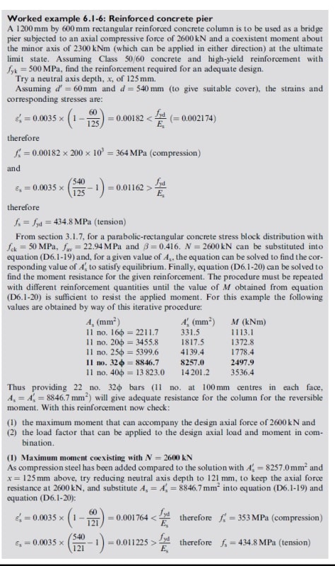
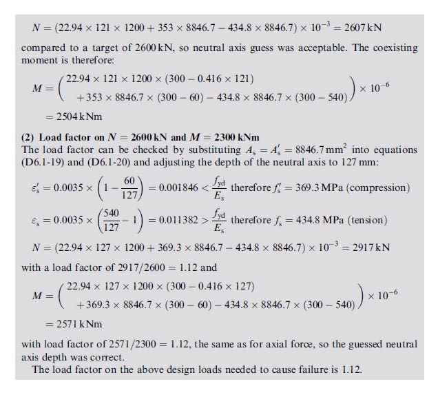
Theres a good worked example in Designers Guide to EN 1992-2 that goes through the procedure but basically as rapt says:

1. Guess the location of the netural axis.
2. Calculate the strain at the relevant location based on your assumption of the NA
3. Calculate the force in the concrete and steel - check theyre the same, if not start again...

Search for Oasys Adsec online I'm pretty sure you can get a free trial, I believe a poster on here also offers a spreadsheet which would also do the job well.
 
Thanks guys. Trying to build in Mathcad, not do by hand just having trouble finding a good example. Don't do much design these days. I'll check out that adsec software for some guidance.
 
A few important considerations/assumptions in determining stresses:-

Usually the tensile strength of the concrete is ignored if the service moment is greater than the cracking moment of the concrete section (similar to determining the ULS capacity).

Concrete stress block is assumed to be linear (triangular) over the depth (max at extreme compression fiber and zero at neutral axis).

Remember that because everything is elastic (hopefully) at the SLS that both stresses and strains are proportional to the distance from the neutral axis. This results in a closed-form solution that involves solving a quadratic for the neutral axis depth, no guessing required.

Remember for any reinforcement in the compression area that the simplest way is to work is in terms of effective compression stress (total stress in reinforcement = concrete stress + effective steel stress), this means effectively you can calculate the concrete component without needing to take off the bits occupied by the bars, and add in the additional extra effective forces and stresses over and above this at the bar locations. To work out actual compression bar stress, remember to add in the concrete stress at the bars location to the effective steel stress.

See attached example from some university notes, very old now but should give you some guidance on the process for working it out.
 
 https://files.engineering.com/getfile.aspx?folder=4918dbbf-2701-4210-9065-880523af6759&file=SLS_Limit_State_(Lecture_Notes).pdf
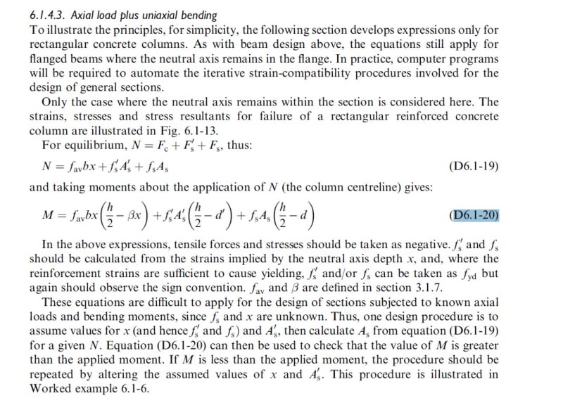
Like Rapt, I've attached some relevant extracts to help you out as the question was well-written :)
Note that the design is checked to Eurocode 2 but the principle should be the same.
If theres any equations you're missing let me know and I'll hook them out.
Cool project gl

pg3_z5eoe5.jpg

pg4_u4hut3.jpg

eqns_d0ualy.jpg


You can find the depth of the NA with a fairly simple cubic equation:


If using MATLAB you can use that to solve the cubic, or you can do it iteratively, or there are Excel VBA functions included in:


The basis of the calculation is that if you assume a maximum compressive concrete stress equal to the depth of the NA (in any consistent units), then the second moment of area (I) of the transformed section about the NA is equal to the applied moment, and the first moment of area (Q) is equal to the applied force, so I/Q = eccentricity of applied force, measured from the NA.

If the applied force is zero, then Q = 0, and the equation for the NA reduces to a quadratic.

Doug Jenkins
Interactive Design Services
 
I think I got it. Thanks so much for everyone's help and input. Couldn't have done it without you. Attached is the part of the Mathcad sheet that I calculated it. Looks to be correct as best I can tell, but if anyone sees any problems please feel free to let me know. Thanks again!
 
 https://files.engineering.com/getfile.aspx?folder=a682c446-cb7c-417a-bc89-527e56e18bc9&file=Axial_and_Bending.pdf
Status
Not open for further replies.

Part and Inventory Search

Sponsor