Continue to Site

Eng-Tips is the largest engineering community on the Internet

Intelligent Work Forums for Engineering Professionals

  • Congratulations KootK on being selected by the Eng-Tips community for having the most helpful posts in the forums last week. Way to Go!

How to calculate the center of gravity of a steel pipe with a weight to the side (middle)? 1

Status
Not open for further replies.

StathPol12

Aerospace
Jan 4, 2016
19
Hi guys,

I have a steel pipe with the dimensions shown below:

Length of the pipe = 6.4 metres.
External diameter = 2.48 metres.
Internal diameter = 2.46 metres.
Self-weight of the steel pipe = 6766.85 kg (uniform steel pipe).

A steel door of 120 kg is bolted to the right side of the steel pipe, in the middle. Can you please help me with calculating the centre of gravity?

Please see attached image.
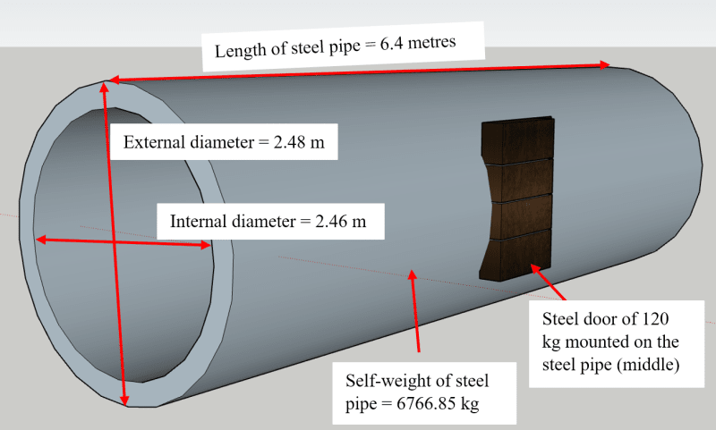
Pipe_shdgtg.png
 
Replies continue below

Recommended for you

The width of the chain anchor points relative to the pipe diameter is significant.
You are showing the chains at an angle.
The angle is significant.

--------------------
Ohm's law
Not just a good idea;
It's the LAW!
 
Given the geometry I think it isn't redundant. Cutting any of the four chains/cables would allow the assembly to move to a new equilibrium position.
 
Depending on the anchorage location, cutting a chain can become unstable. You cannot push on a chain, if I recall. I always like saddles, myself.

-----*****-----
So strange to see the singularity approaching while the entire planet is rapidly turning into a hellscape. -John Coates

-Dik
 
you know the weight of the total thing (pipe and door) and you know the CG of the total thing ... put the weight at the CG and calculate from there.

you can analyze like a simply supported beam ... read up on that. Basically look at the XZ plane ... weight down, and two vertical reactions (two because the two points at each end line up, yes?). Your CG is at the mid-span yes? if the lift points are equally distant from the mid-pt (from the CG) then each end will support 1/2 the weight. But how to distribute this between the two lifts (at either end).

look at the pipe in the YZ plane. Again the weight is down and in this view you see two lifts (for the same reason as before, yes?) but here the CG is slightly to one side (there is a small Y value to the total CG). So the XZ solution told you that the weight at the ends is 1/2 the weight) so now you can solve the vertical reactions for the load (weight) not being exactly in the middle.

So now you know the vertical load in each lift. But your lifts don't "look" vertical. If the lifts are angled find the length of the lift and it's vertical component, then the load in the inclined lift = (lift_length/lift_vertical_component)*vertical_load. yes?

And Greg has a point, you should state your assumptions (in order to solve the indeterminate problem). And the key assumption is that each support has the same stiffness (and you should understand why).

"Hoffen wir mal, dass alles gut geht !"
General Paulus, Nov 1942, outside Stalingrad after the launch of Operation Uranus.
 
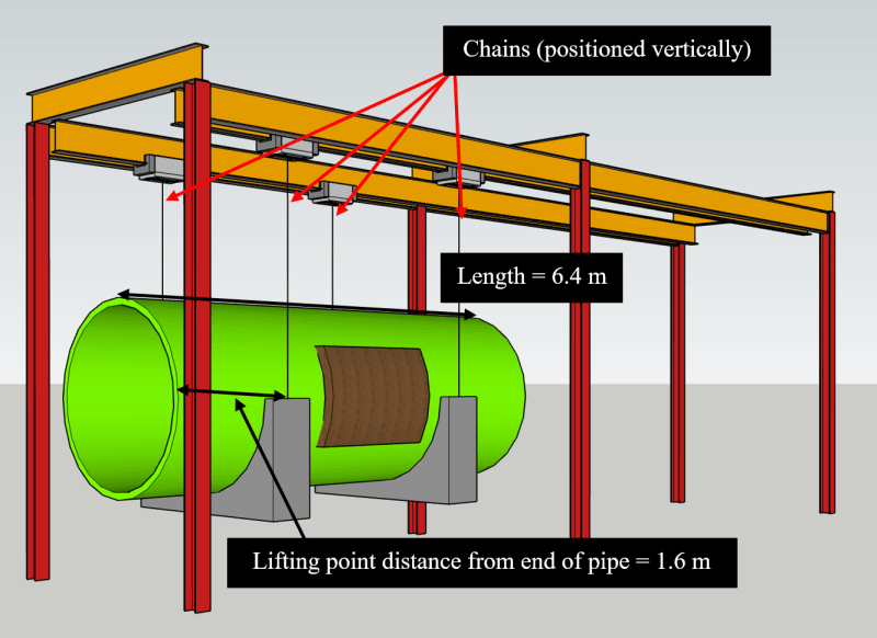
rb1957 The chains will be positioned vertically, I did a small error on the previous drawing - just spent some time to correct it and here how it looks. I also did a small error in the weight of the pipe and corrected it. We have the following:

We know that:

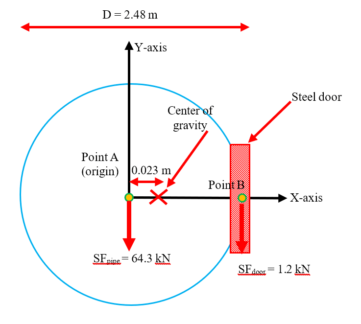
- Weight (self-weight) of the pipe is 64.3 kN (6550 kg)
- Weight (self-weight) of the door is 1.2 kN (120 kg)
- Total self-weight of pipe and door is 65.5 kN (ignore the saddles for now).

From the calculations, we also know that the center of gravity due to the door attachment will shift 0.023 m to the right from the center point of the pipe (If we assume the datum is the center of the pipe only).

Image_2_zlweup.png


I am trying to work out the load each chain will take in order to put them as point loads on the steel beams. We know that the chains to the side where the door is located will take slightly higher point loads than the other side

What confuses and cannot work out the load in each chain, is how to consider the shift of the center of gravity (0.023m) due to the door. Lifting points are at quarter points (1.6 m from each end of the 6.4 m pipe).

Image1_r5rbul.png
 
think about it ... I'm not going to do it for you.

I've said each end (with two chains) reacts 1/2 the load ... and you understand why ?
Look at the structure in the YZ plane ... things appear, at least, to be symmetric.

So consider each end in the XY plane, with two chains and 1/2 the load, as a simply supported beam; look this up if you don't know what that means for the analysis.
The load is positioned at the X CG, slightly off the mid-point between the two lifts.
I may have confused you as I had mentally up the Z axis up, X along, Y lateral (to the Left, why?)

and what are the two grey things, joining the lifts ...how much do they weigh ? ('cause the chains supports their weight too)

"Hoffen wir mal, dass alles gut geht !"
General Paulus, Nov 1942, outside Stalingrad after the launch of Operation Uranus.
 
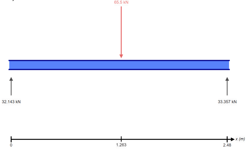
I took the XY plane put the total load of 65.5 kN (sum of pipe and door) on the shifted center of gravity point as shown above. Then, I solved it as a simply supported beam.


21_sewbcr.png


If this is correct, then

16.0715 kN on the each of the two chains located to the side of the pipe without the door
16.6785 kN on the each of the two chains located to the side of the pipe with the door

(16.0715 x 2) + (16.6785 x 2)= 65.5 kN..no?
 
that seems reasonable.

what about the grey things (joining the lifts) ?

"Hoffen wir mal, dass alles gut geht !"
General Paulus, Nov 1942, outside Stalingrad after the launch of Operation Uranus.
 
Status
Not open for further replies.

Part and Inventory Search

Sponsor